Buffer control circuit and buffer control method of motor device

A technology for buffer control and motor equipment, applied in the field of power electronics, can solve the problems of inability to ensure the safety of motor equipment and complex structure, and achieve the effect of simple structure, ensuring safety, and reducing input current

Inactive Publication Date: 2016-08-31
INVT POWER ELECTRONICS SUZHOU CO LTD
View PDF8 Cites 4 Cited by
  • Summary
  • Abstract
  • Description
  • Claims
  • Application Information

AI Technical Summary

Problems solved by technology

[0004] The purpose of the present invention is to provide a buffer control circuit and a buffer control method for motor equipment, to solve the problems in the prior art due to the use of auto-depressor isolation and step-down starting or switching mode or the use of star-delta step-down connection starting or switching mode , the structure is more complex, and the safety of the electrical equipment cannot be guaranteed

Method used


Image

  • Buffer control circuit and buffer control method of motor device
  • Buffer control circuit and buffer control method of motor device
  • Buffer control circuit and buffer control method of motor device

Examples


Embodiment Construction

[0044] The following will clearly and completely describe the technical solutions in the embodiments of the present invention with reference to the accompanying drawings in the embodiments of the present invention. Obviously, the described embodiments are only some, not all, embodiments of the present invention. Based on the embodiments of the present invention, all other embodiments obtained by persons of ordinary skill in the art without making creative efforts belong to the protection scope of the present invention.

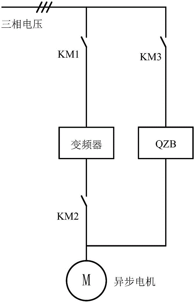
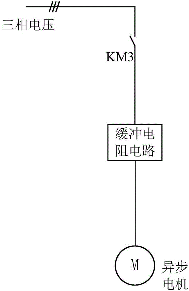
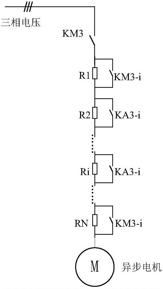
[0045] The problem to be solved by the present invention is to propose a simple and convenient buffer control circuit and buffer control for power frequency startup or switching in combination with the method of step-down startup or switching in view of the shortcomings in the background technology such as complex connection of power frequency startup or switching mode method, the general idea of ​​the control method is: use the voltage division effect of the r...


PUM


Abstract

The invention discloses a buffer control circuit and a buffer control method of a motor device. Startup operation of the motor device M is realized through a buffer resistance circuit, and the input voltage of the motor voltage M is reduced by using the voltage division effect of a resistor for the input voltage, so that the input current of the motor device M is reduced. The used buffer resistance circuit is relatively simple in structure, and the safety of the motor device M is guaranteed.

Description

technical field [0001] The present invention relates to the technical field of power electronics, and more specifically, to a buffer control circuit and a buffer control method for motor equipment. Background technique [0002] When the motor equipment is in use, if it is started directly at power frequency (50Hz), the start-up impulse current generated due to the large line voltage drop will reach seven or eight times the rated current, or even greater, and multiple current impacts will cause damage to the electrical equipment Or cause the front circuit breaker to trip, so soft start equipment, such as frequency converter, is required. When the inverter equipment is in good condition, the phase-locked switching method can be used for frequency conversion and power frequency switching. However, when the frequency converter equipment is damaged or the frequency converter cannot be used, and it is necessary to start at power frequency or switch from frequency conversion to pow...

Claims


Application Information

Patent Timeline
IPC IPC(8): H02P1/34
CPCH02P1/34
Inventor 李忠锋陈杰申大力
Owner INVT POWER ELECTRONICS SUZHOU CO LTD
Why Eureka
Try Eureka