Energy-saving motor for hydraulic pump drive

A technology of hydraulic pumps and drive circuits, applied in the direction of connection with control/drive circuits, electrical components, electromechanical devices, etc., can solve problems such as waste of electric energy, easy to burn out, heat loss of motors, etc., to avoid excessive heat generation, protect motors, The effect of protecting energy saving

Inactive Publication Date: 2012-11-28
DONGGUAN SHENYU MACHINERY +1
View PDF5 Cites 3 Cited by
  • Summary
  • Abstract
  • Description
  • Claims
  • Application Information

AI Technical Summary

Problems solved by technology

When the motor is working, a large amount of heat energy will be generated when the current passes through the coil winding, which not only causes serious heat loss of the motor, but also affects the power conversion efficiency of the motor when it is working, and the defects are more obvious
[0003] In addition, ordinary motors cannot adjust the input current of the motor according to the change of the motor load. When the load of the motor becomes larger, the speed of the motor will decrease, and may even stop. If the rated current is still input at this time, the input All the electric energy will be converted into heat energy by the coil windings, which not only causes a serious waste of electric energy, but also easily burns out the coil windings of the motor, thus causing the motor to be scrapped, and even cause a fire in severe cases, which poses a serious safety hazard

Method used


Image

  • Energy-saving motor for hydraulic pump drive
  • Energy-saving motor for hydraulic pump drive
  • Energy-saving motor for hydraulic pump drive

Examples


Embodiment Construction

[0019] In order to facilitate the understanding of those skilled in the art, the present invention will be further described below in conjunction with the embodiments and accompanying drawings, and the contents mentioned in the embodiments are not intended to limit the present invention.

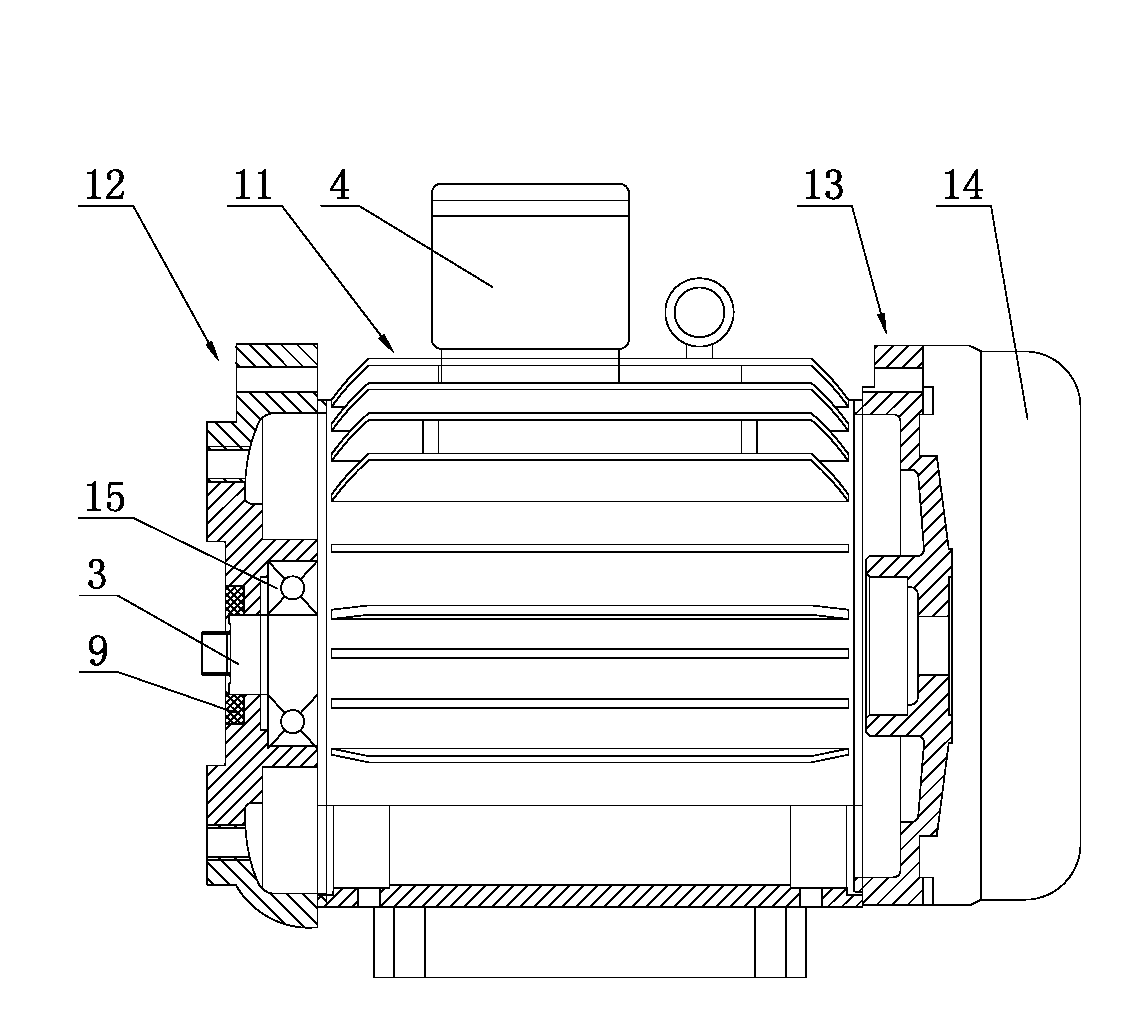
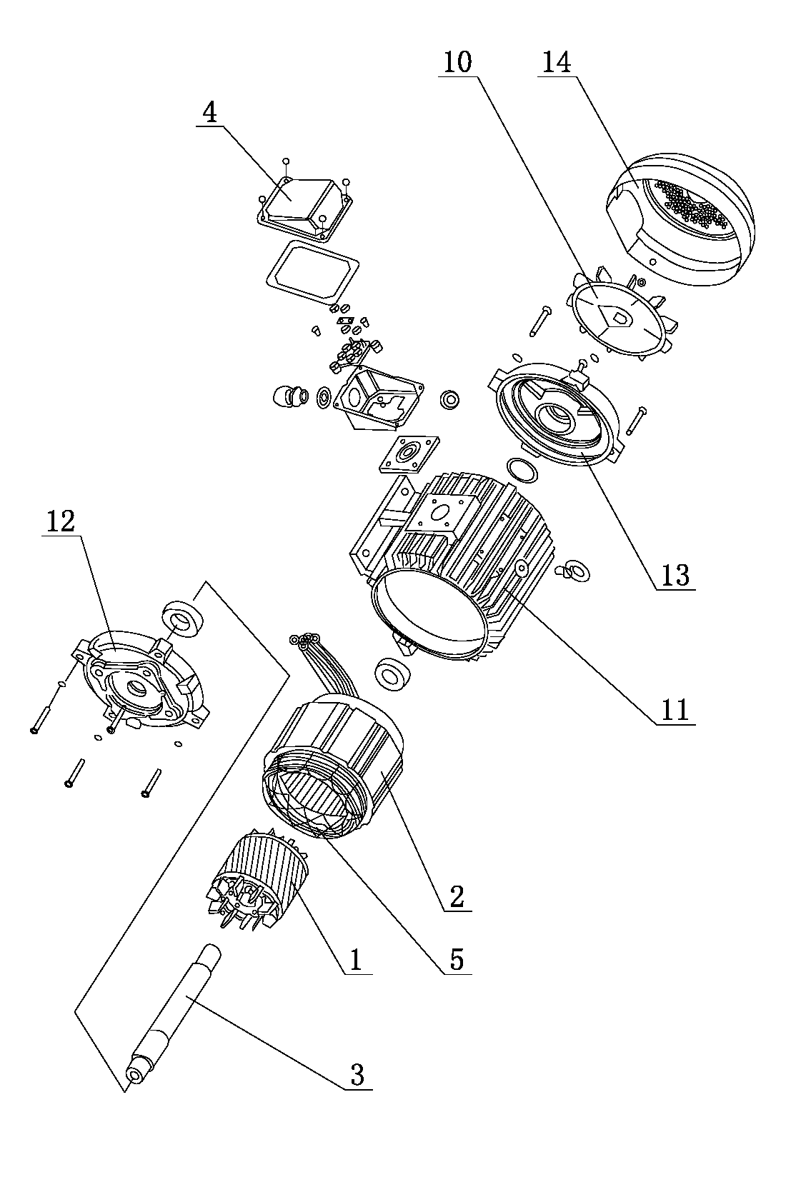
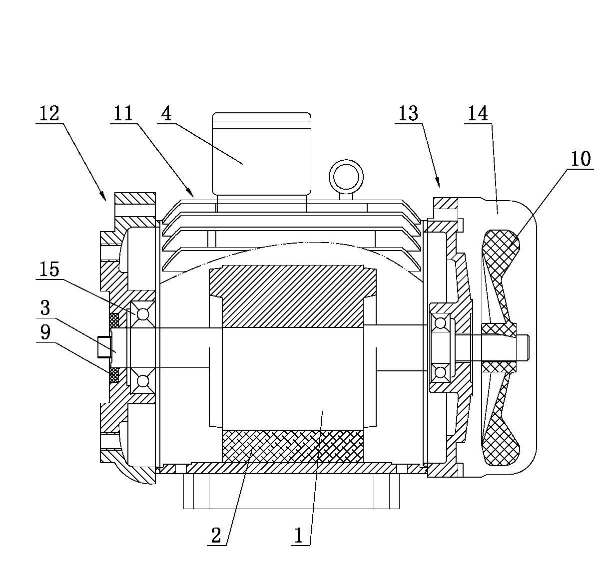
[0020] as attached Figure 1 to Figure 4 As shown, an energy-saving motor for driving a hydraulic pump includes a rotor 1, a stator 2, a rotating shaft 3 and a motor casing, the stator 2 is fixed on the inner wall of the motor casing, the rotating shaft 3 passes through the stator 2, the rotor 1 is located inside the stator 2, and the rotating shaft 3 The two ends of the motor are connected to the motor shell, the motor shell is equipped with a junction box 4, the stator 2 is equipped with a coil winding 5, and the junction box 4 is equipped with a terminal 6, a processor 7, a drive circuit 8 and a drive circuit for detecting The detection device 19 of the output current of the circuit 8 , t...


PUM


Abstract

The invention relates to the technical field of hydraulic control drive, and in particular relates to an energy-saving motor for hydraulic pump drive. The energy-saving motor comprises a rotor, a stator, a rotating shaft and a motor shell, wherein the motor shell is provided with a junction box; the stator is provided with a coil winding; the junction box is provided with a wiring terminal, a processor, a driving circuit and a detection device for detecting the output current of the driving circuit; and the detection device, the wiring terminal and the driving circuit are electrically connected with the processor. When the motor has an extremely high load, the rotating speeds of the rotor and rotating shaft of the motor are reduced, the heating capacity of the coil winding is improved, the resistance of the coil winding is increased, the input current of the motor is reduced, namely the output current of the driving circuit is reduced, the processor obtains the control information by comparing the detected current information with the set limit data and transmits the control information to the driving circuit, and the motor is prevented from being excessively heated by reducing or cutting off the output current of the driving circuit; and therefore, the functions of protecting the motor and saving the energy are realized.

Description

technical field [0001] The invention relates to the technical field of hydraulic control driving, in particular to an energy-saving motor for driving a hydraulic pump. Background technique [0002] The motor is a common device that converts electrical energy into mechanical energy. It generally includes a rotor, a stator, a rotating shaft and a motor housing. The stator is fixed on the inner wall of the motor housing. The rotating shaft passes through the stator. The rotor is located inside the stator. The two ends of the rotating shaft are connected to the motor housing. Connection, the motor casing is equipped with a junction box, and the stator is equipped with coil windings. When the motor is working, a large amount of heat energy will be generated when the current passes through the coil winding, which not only causes serious heat loss of the motor, but also affects the power conversion efficiency of the motor when it is working, and the defects are more obvious. [00...

Claims


Application Information

Patent Timeline
Patent Type & Authority Applications(China)
IPC IPC(8): H02K11/00H02K5/04H02K9/06H02K5/124H02H7/085H02K11/33
Inventor 李志李安歌李鑫
Owner DONGGUAN SHENYU MACHINERY
Why Eureka
Try Eureka