

Seal ring
A sealing ring and side wall surface technology, which is applied in the field of sealing rings, can solve the problems of reducing rotation torque and achieve the effect of suppressing leakage
- Summary
- Abstract
- Description
- Claims
- Application Information
AI Technical Summary
Problems solved by technology
Method used
Image


Examples
Embodiment 1
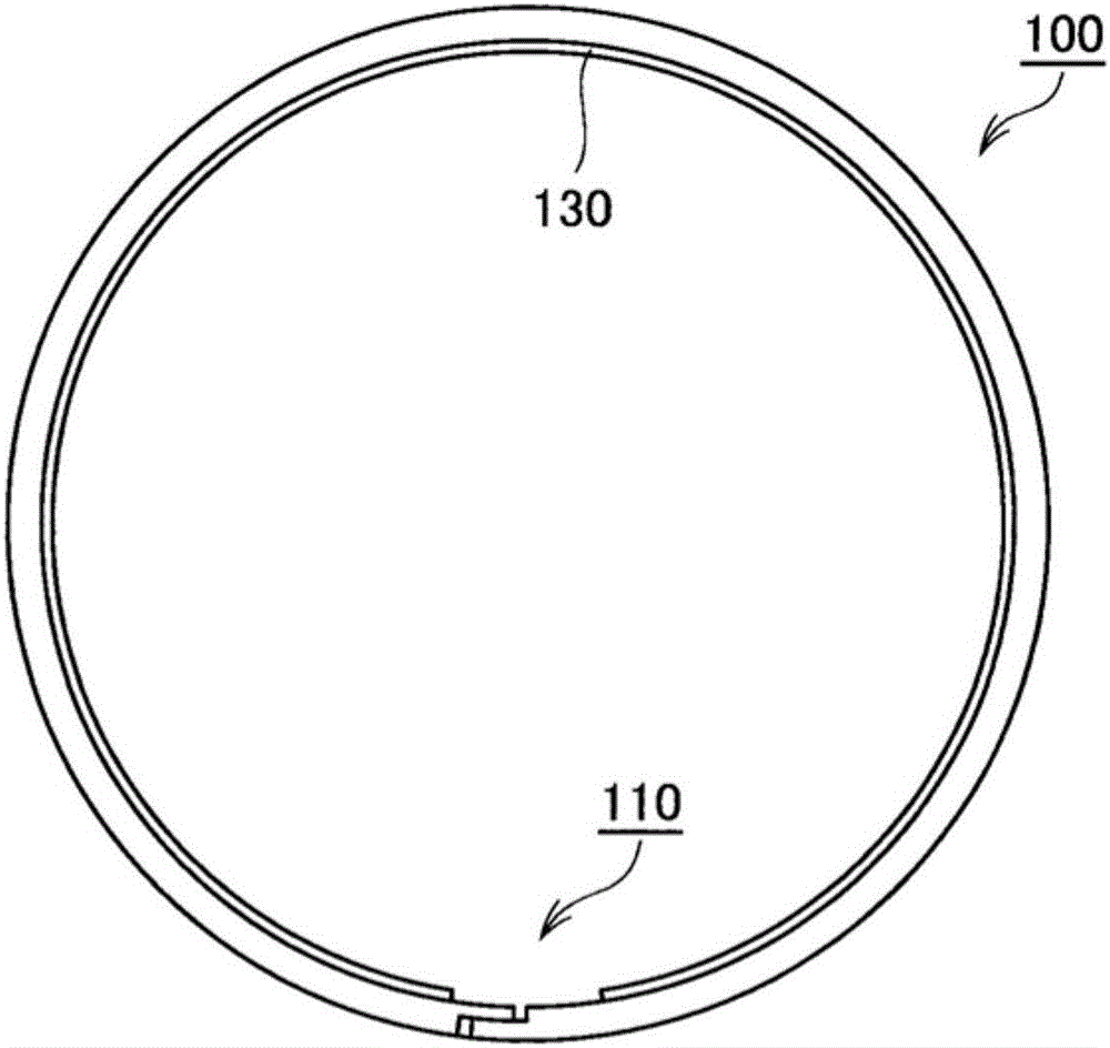
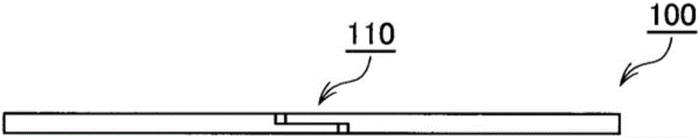
[0050] refer to Figure 1 to Figure 12 A seal ring according to an embodiment of the present invention will be described. figure 1 It is a side view of the sealing ring of Example 1 of the present invention. also, figure 1 Indicates the side surface opposite to the sliding surface in the seal. figure 2 This is a view of the seal ring according to Example 1 of the present invention viewed from the outer peripheral surface side. image 3 It is a side view of the sealing ring of Example 1 of the present invention. also, image 3 Indicates the side surface on the sliding surface side of the seal. Figure 4 It is a partial enlarged view of the side view of the seal ring in Embodiment 1 of the present invention. also, Figure 4 to enlarge image 3 A figure in the vicinity of the seam portion 110 is provided in . Figure 5 It is a schematic cross-sectional view of the seal ring of Example 1 of the present invention. also, Figure 5 for image 3 AA sectional view in . F...
Embodiment 2
[0069] Figure 13 to Figure 19 Example 2 of the present invention is shown, and the structure in the case where, in the present example, the depth of the part connected to the second groove in the first groove of the dynamic pressure generating groove is configured to be the same as that of the second groove The depths are the same, and are deeper than the depth except for the connection portion of the first groove with the second groove. Since other structures and functions are the same as those of Embodiment 1, the same symbols are assigned to the same structural parts and their descriptions are omitted.
[0070] Figure 13 It is a partial enlarged view of the side view of the seal ring in Embodiment 2 of the present invention, and is equivalent to that in Embodiment 1 above. Figure 4 diagram. Figure 14 ~ Figure 19 It is a schematic sectional view of the sealing ring according to the second embodiment of the present invention. also, Figure 14 ~ Figure 19 for Figure...
PUM
 Abstract
Description
Claims
Application Information