A gas dust removal filter element fixing device and method thereof

A gas dust removal and fixing device technology, applied in separation methods, chemical instruments and methods, transportation and packaging, etc., can solve the problems of easy brittle fracture, non-vertical installation of ceramic filter elements, etc. Avoid the effect of dust trellis

Active Publication Date: 2017-12-22
HENAN DRAGON INTO COAL TECH CO LTD
View PDF6 Cites 0 Cited by
  • Summary
  • Abstract
  • Description
  • Claims
  • Application Information

AI Technical Summary

Problems solved by technology

[0010] In view of this, the object of the present invention is to address the deficiencies of the prior art, to provide a gas dust removal filter element fixing device and its method, to solve the problem that the ceramic filter element is prone to brittle fracture due to non-vertical installation and back-blowing swing, and at the same time avoid dust Scaffolding problems, which can improve the service life of the filter element, reduce the time spent on maintenance, and reduce production costs

Method used


Image

  • A gas dust removal filter element fixing device and method thereof
  • A gas dust removal filter element fixing device and method thereof
  • A gas dust removal filter element fixing device and method thereof

Examples


Embodiment 1

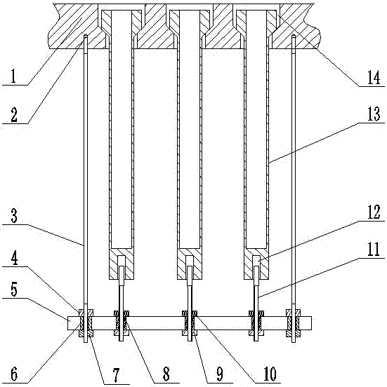
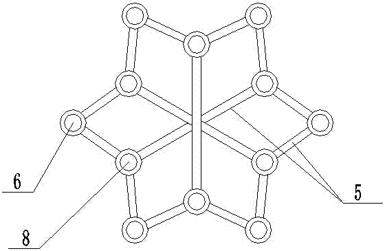
[0036] Such as figure 1 , figure 2 As shown, a gas dust removal filter element fixing device includes a partition 1, a filter element 13 arranged on the partition 1 and a filter element bracket arranged under the partition 1, and the tail of the filter element 13 is provided with a groove 12. The separator 1 is provided with several counterbores 14 whose shape matches the head of the filter element 13 , and the head of the filter element 13 is arranged in the counterbores 14 on the separator 1 .

[0037] The filter element bracket includes a sleeve I6, a sleeve II8 and a strip 5, and the strip 5 connects the sleeve I6 and the sleeve II8 together.

[0038] A plurality of threaded holes 2 are provided on the lower surface of the partition 1, and the threaded holes 2 are internally threaded to connect with a pull rod 3, and the lower end of the pull rod 3 is penetrated and arranged in the setting sleeve I6.

[0039] The distance between the separator 1 and the filter element b...

Embodiment 2

[0051] Such as image 3 , Figure 4 As shown, a gas dust removal filter element fixing device includes a separator 1, a filter element arranged on the separator 1 and a filter element bracket arranged below the separator 1, and a groove 12 is provided at the tail of the filter element. Several counterbores 14 whose shapes match the head of the filter element are arranged on the partition 1 , and the filter head is arranged in the counterbore 14 on the partition 1 .

[0052] The filter element bracket includes a sleeve I6, a sleeve II8 and a strip 5, and the strip 5 connects the sleeve I6 and the sleeve II8 together.

[0053] A plurality of threaded holes 2 are provided on the lower surface of the partition 1, and the threaded holes 2 are internally threaded to connect with a pull rod 3, and the lower end of the pull rod 3 is penetrated and arranged in the setting sleeve I6.

[0054] The distance between the separator 1 and the filter element bracket is adjusted by the upper ...


PUM


Abstract

The invention discloses a gas dust removal filter element fixing device, which comprises a separator, a filter element arranged on the separator and a filter element bracket arranged under the separator. A counterbore whose shape matches the head of the filter element, the head of the filter element is sleeved in the counterbore; the lower surface of the partition is threaded with several pull rods, and the filter element bracket is connected with the pull rods A sleeve I is arranged at the corresponding position, and the lower end of the pull rod is pierced in the sleeve I, and the distance between the partition plate and the filter element bracket is adjusted by an adjustment member arranged at the lower end of the pull rod; The tail of the filter element is guided and positioned through an adjusting screw arranged on the filter element bracket. The invention solves the problem that the ceramic filter element is prone to brittle fracture due to non-vertical installation and back-blowing swing, and at the same time avoids the problem of dust scaffolding, thereby improving the service life of the filter element, reducing maintenance time, and reducing production costs.

Description

technical field [0001] The invention relates to a filter element fixing method, in particular to a gas dust removal filter element fixing device and method thereof. Background technique [0002] High-temperature gas dedusting technology uses high-temperature filter media (metal or ceramic filter materials) to directly dedust and purify gas under high-temperature conditions. Under these conditions, the process strengthens the reaction to realize the clean discharge of gas. At the same time, the process can be simplified, the investment in process equipment can be saved, water resources can be saved, and secondary water pollution caused by wet dust removal can be avoided. High-temperature gas dedusting technology has broad application prospects in energy, petrochemical, steel, building materials and other industrial fields. [0003] The integrated combined cycle power generation technology "Coal Gasification Combined Cycle Power Generation (IGCC)" is a new power generation te...

Claims


Application Information

Patent Timeline
Patent Type & Authority Patents(China)
IPC IPC(8): B01D46/00
CPCB01D46/0005B01D46/60
Inventor 朱书成王希彬
Owner HENAN DRAGON INTO COAL TECH CO LTD
Why Eureka
Try Eureka