Electric clamping jaw

A gripper and electric technology, which is applied in the field of robot systems, can solve problems such as thin-walled parts deformation, insufficient clamping force, and workpiece slippage, and achieve the effect of not being easy to slip or deform

Inactive Publication Date: 2016-09-07
四川东巨自动化科技有限公司
View PDF6 Cites 35 Cited by
  • Summary
  • Abstract
  • Description
  • Claims
  • Application Information

AI Technical Summary

Problems solved by technology

[0003] The existing electric gripper must manually consider the size, material, contact area, friction coefficient and other parameters of the workpiece before grabbing the workpiece, and manually calculate the appropriate clamping force of the workpiece. The calculation process needs to be completed by professional engineers. The current industrial In the automatic production line, the workpieces are often small batches and multi-models. The complex calculation reduces the industrial production efficiency, and the rigid clamping force is prone to insufficient clamping force to cause workpiece slippage or large clamping force to produce thin-walled parts. The problem of deformation, so the market urgently needs an electric gripper that can automatically calculate and automatically adjust the clamping force

Method used


Image

  • Electric clamping jaw
  • Electric clamping jaw
  • Electric clamping jaw

Examples


Embodiment Construction

[0029] The following will clearly and completely describe the technical solutions in the embodiments of the present invention with reference to the accompanying drawings in the embodiments of the present invention. Obviously, the described embodiments are only some, not all, embodiments of the present invention. Based on the embodiments of the present invention, all other embodiments obtained by persons of ordinary skill in the art without making creative efforts belong to the protection scope of the present invention.

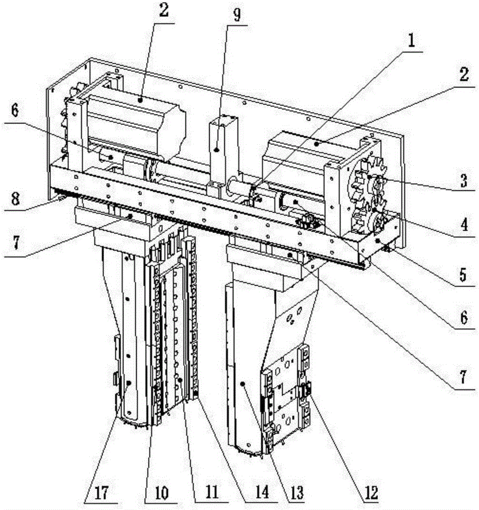
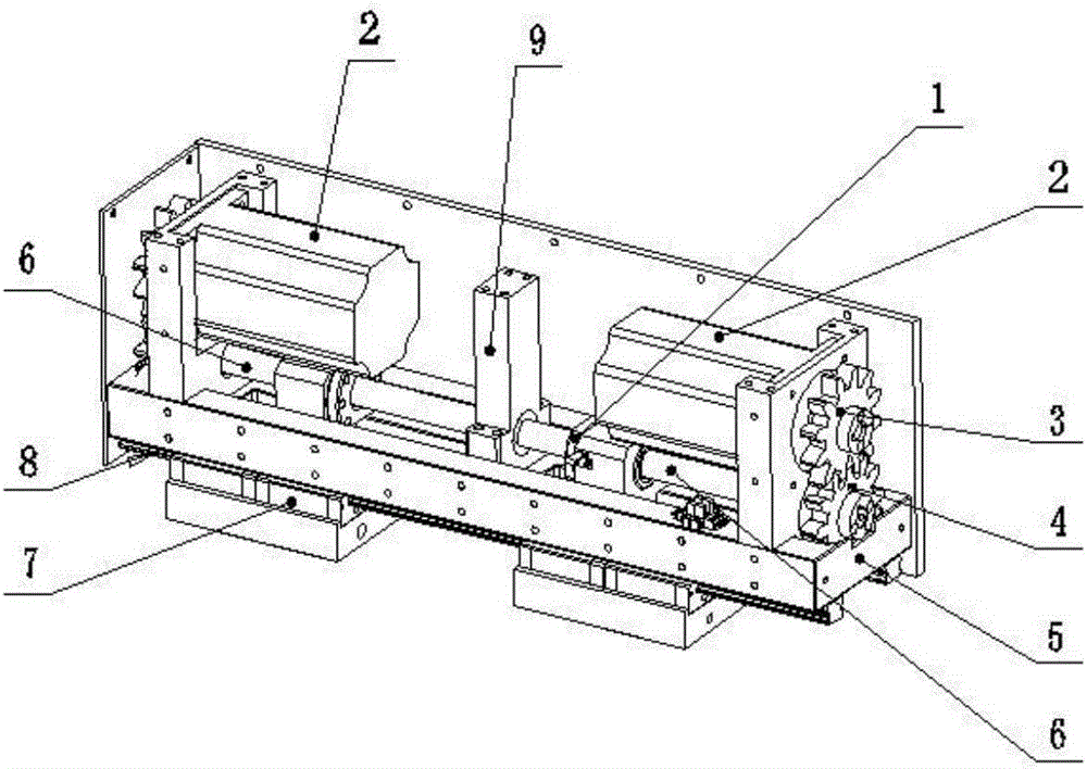
[0030] Such as figure 1 and figure 2 As shown, an electric gripper includes a driving part and a gripper, the gripper includes a first gripper 13 and a second gripper 17, a mounting plate 5 is provided at the bottom of the driving part, and the top of the mounting plate 5 is along the clamping direction There are two ball screws 6 symmetrically, one end of the ball screw 6 is installed with a driven gear 4, the driven gear 4 is connected with the main gear 3...


PUM


Abstract

An electric clamping jaw comprises a driving part and a clamping jaw body; the clamping jaw body is mounted on the bottom of the driving part and comprises a first clamping jaw and a second clamping jaw; the first clamping jaw and the second clamping jaw are both connected with a driving mechanism, and the clamping jaw body is provided with a slippage detection sensing system and a deformation sensing system; and according to the electric clamping jaw, clamping force can be automatically calculated and adjusted.

Description

technical field [0001] The patent of the present invention relates to a robot system, in particular to an electric gripper. Background technique [0002] In the automatic operation of picking and placing materials by the robot, the robot gripper needs to load the parts on the jig of the machine. After the parts are processed, the robot gripper removes the parts from the jig of the machine. When removing parts from the jig of the machine, the robot gripper does not need high positioning accuracy. However, when the robot gripper grabs the parts stacked in the material tray, the parts stacked in the material tray may shift Irregular placement requires the robot gripper to have a larger adaptability range. At the same time, it also requires the robot gripper to accurately position the part in order to accurately grab the part onto the machine. [0003] The existing electric gripper must manually consider the size, material, contact area, friction coefficient and other parameter...

Claims


Application Information

Patent Timeline
Patent Type & Authority Applications(China)
IPC IPC(8): B25J9/12B25J15/02B25J13/08
CPCB25J9/123B25J13/08B25J15/026B25J13/083
Inventor 高超平蒋晴
Owner 四川东巨自动化科技有限公司
Why Eureka
Try Eureka