Wind distribution device facilitating discharging of big particle matter and multi-flow circulating fluidized bed boiler

A technology of circulating fluidized bed and air distribution device, which is applied in the directions of fluidized bed combustion equipment, fuel burning in a molten state, lighting and heating equipment, etc., to achieve the effect of being beneficial to slag discharge

Active Publication Date: 2016-09-07
BEIJING NOWVA ENERGY TECH CO LTD
View PDF5 Cites 7 Cited by
  • Summary
  • Abstract
  • Description
  • Claims
  • Application Information

AI Technical Summary

Problems solved by technology

[0005] The purpose of the present invention is to solve the problems existing at present, and provide an air distribution device and a circulating fluidized bed boiler that are conducive to the discharge of large particles, which can smoothly discharge large particles that interfere with the uniform air output of the air distribution plate, thereby ensuring that the air in the furnace is The material is continuously and evenly fluidized

Method used


Image

  • Wind distribution device facilitating discharging of big particle matter and multi-flow circulating fluidized bed boiler
  • Wind distribution device facilitating discharging of big particle matter and multi-flow circulating fluidized bed boiler
  • Wind distribution device facilitating discharging of big particle matter and multi-flow circulating fluidized bed boiler

Examples


Embodiment 1

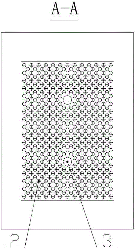
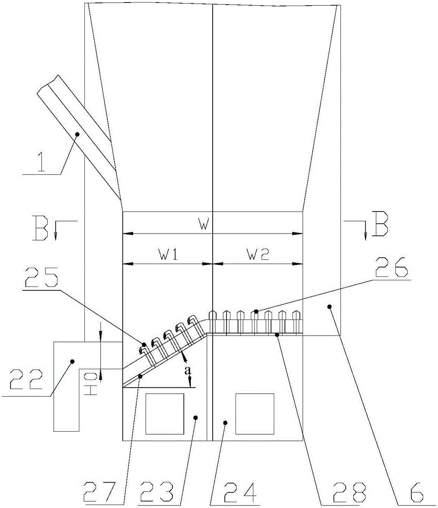
[0045] The invention provides an air distribution device which is beneficial to discharge large particles, and its structure is as follows Figure 3-Figure 4 Shown, including:

[0046] The slag pipe 22, the first air chamber 23, the second air chamber 24, the first air cap 25, the second air cap 26, the inclined air distribution plate 27, and the horizontal air distribution plate 28.

[0047] The horizontal air distribution plate 28 is arranged horizontally, and the inclined air distribution plate 27 is inclined downward from one end edge of the horizontal air distribution plate 28 and is set in the middle of the furnace of the circulating fluidized bed boiler after being butted with the horizontal air distribution plate 28; 28 and the remaining edges of the inclined air distribution plate 27 are welded to the inner ring of the furnace through steel plates; the horizontal width of the horizontal air distribution plate 28 is recorded as W1; the horizontal projection width of the inc...

Embodiment 2

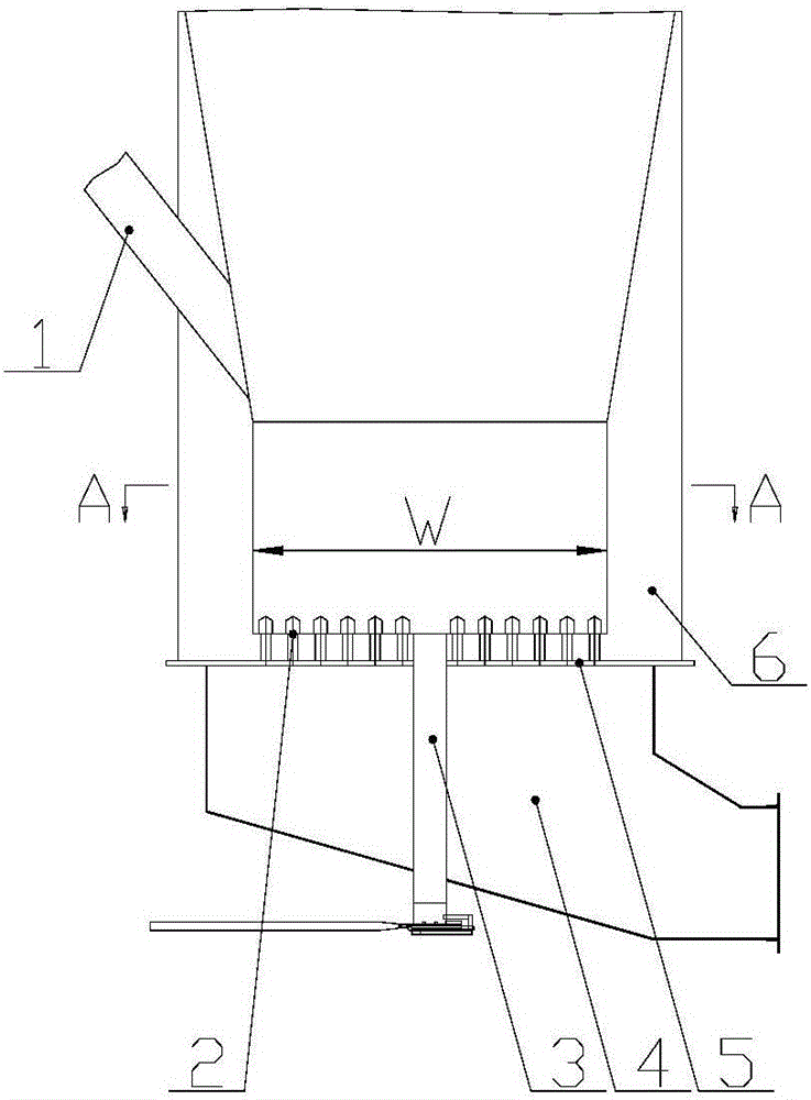
[0068] The present invention also provides a circulating fluidized bed boiler, which includes: the air distribution device that facilitates the discharge of large particles in the first embodiment, the feed pipe 1 and the furnace wall 6.

[0069] The furnace wall 6 is a fire-resistant, wear-resistant and heat-preserving furnace wall. The surrounding interior is a furnace. The inclined air distribution plate 27 and the horizontal air distribution plate 28 in the air distribution device that facilitate the discharge of large particles are arranged in the middle of the furnace, and the horizontal air distribution is A number of second air hoods 26 are arranged staggered on the plate 28, with independent air chambers for air supply; on the inclined air distribution plate 27, a number of first air hoods 25 are arranged in line, and an independent air chamber is arranged for air supply; At the lowest point of the lower end of the inclined air distribution plate 27, there is a gate valve...


PUM


Abstract

The invention relates to a wind distribution device facilitating discharging of big particle matter and a multi-flow circulating fluidized bed boiler. A horizontal wind distribution plate (28) of the wind distribution device is arranged horizontally. An inclined wind distribution plate (27) inclines downwards from one edge of the horizontal wind distribution plate (28), is in butt joint with the horizontal wind distribution plate (28) and then is arranged in the middle of a hearth. Other edges of the horizontal wind distribution plate (28) and other edges of the inclined wind distribution plate (27) are fixed to the inner ring of the hearth. A plurality of second wind caps (26) are arranged on the horizontal wind distribution plate (28). A plurality of first wind caps (25) capable of directionally outputting wind are arranged on the inclined wind distribution plate (27). A first wind chamber (23) supplies wind to the inclined wind distribution plate (27). A second wind chamber (24) supplies wind to the horizontal wind distribution plate (28). Slag dropping pipes (22) are arranged on the same side of the inclined wind distribution plate (27) and located in the lowest position of an inclined section. The wind distribution device can smoothly discharge the big particle matter disturbing uniform outlet air of the wind distribution plates, and accordingly it can be guaranteed that materials in the hearth are fluidized continuously and uniformly.

Description

Technical field [0001] The invention relates to the field of garbage and industrial waste treatment, in particular to an air distribution device and a multi-process circulating fluidized bed boiler that are beneficial to discharging large particles. Background technique [0002] In the process of incineration of garbage and industrial waste in a circulating fluidized bed, continuous and uniform fluidization of the materials in the furnace is the key to ensure that the garbage and industrial waste are successfully processed. [0003] The current circulating fluidized bed boiler structure figure 1 with figure 2 As shown, it includes: a furnace wall 6, a feeding pipe that feeds through the furnace wall 1, an air distribution plate 5 horizontally arranged in the furnace chamber wrapped by the furnace wall 6, an air chamber 4 and a row arranged at the bottom of the air distribution plate 5 Slag pipe 3, a number of wind caps 2 staggered arranged on the air distribution plate 5. [0004] ...

Claims


Application Information

Patent Timeline
Patent Type & Authority Applications(China)
IPC IPC(8): F23C10/20F23C10/24
CPCF23C10/20F23C10/24
Inventor 康建斌王军岗李纹广赵志田
Owner BEIJING NOWVA ENERGY TECH CO LTD
Why Eureka
Try Eureka