Electromagnetic imaging system and method employing oblique incident wave

An imaging system, oblique incidence technology, applied in the radio wave measurement system, using re-radiation, radio wave reflection/re-radiation and other directions, can solve the problems of measurement accuracy and data processing inconvenience

Inactive Publication Date: 2016-09-07
ZHEJIANG UNIV
View PDF4 Cites 11 Cited by
  • Summary
  • Abstract
  • Description
  • Claims
  • Application Information

AI Technical Summary

Problems solved by technology

Due to the possible occlusion between the transmitting and receiving antennas and the mutual coupling between the transmitting and receiving antennas, this has caused inconvenience to the accuracy of the measurement and data processing

Method used


Image

  • Electromagnetic imaging system and method employing oblique incident wave
  • Electromagnetic imaging system and method employing oblique incident wave
  • Electromagnetic imaging system and method employing oblique incident wave

Examples


Embodiment Construction

[0036] The present invention will be further described below with reference to the accompanying drawings.

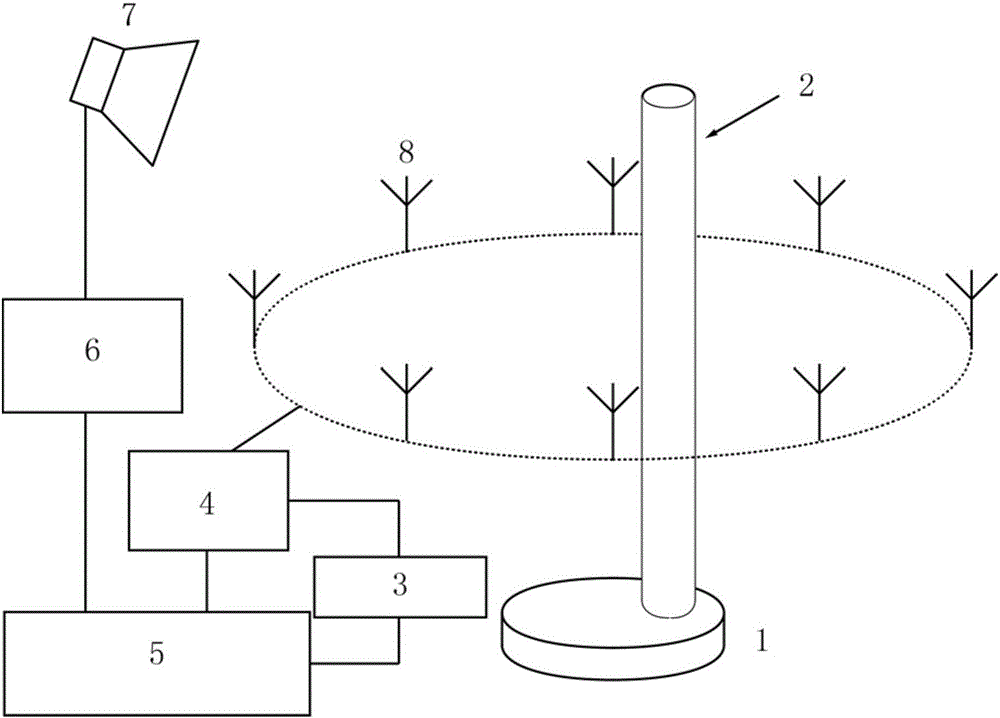
[0037] like figure 1 As shown, the present invention includes a vector network analyzer 5, a radio frequency power amplifier 6, a microwave switching network 4, a turntable 1 and a transceiver antenna, the scatterer 2 is fixed on the turntable 1, and the surrounding of the scatterer 2 is evenly distributed along the circumference. Receiving antennas 8, all receiving antennas 8 are connected to the microwave switching network 4 to work through the required receiving antennas 8 gating through the microwave switching network 4, and the microwave switching network 4 is connected to the input end of the vector network analyzer 5 through a coaxial line, and the vector The output end of the network analyzer 5 is connected to the transmitting antenna 7 via the radio frequency power amplifier 6 , and the transmitting antenna 7 radiates toward the scatterer 2 from obliquely above....


PUM


Abstract

The invention discloses an electromagnetic imaging system and method employing an oblique incident wave. A scatterer is fixed on a rotating platform, and the periphery of the scatterer is uniformly provided with a plurality of receiving antennas at intervals. All receiving antennas are connected to a microwave switching network, and the needed receiving antennas are selected to be connected for operation through the microwave switching network. The microwave switching network is connected with a vector network analyzer, and the vector network analyzer is connected with a transmitting antenna through a radio frequency power amplifier. The incident field data and the total field data after each rotation are obtained firstly, and then the subtraction of the incident field data and the total field data is carried out to obtain the scattering field data of each measurement. An imaging region is equally divided to obtain a Green function, and a target function is built. An optimization algorithm is employed for solving the minimum value of the target function, and the distribution of dielectric constants is obtained. The system and method solve a problem of shading and cross coupling of receiving and transmitting antennas in an electromagnetic imaging system employing normal incident waves. The receiving and transmitting antennas can be flexibly arranged, and the proper incident angles can be freely selected according to the actual conditions.

Description

technical field [0001] The present invention relates to an electromagnetic imaging system, in particular to an electromagnetic imaging system and method using oblique incident waves. Background technique [0002] Electromagnetic waves scatter when their propagation encounters an object that differs in the permittivity or permeability of the background material. By detecting and accurately measuring the scattered field, one can obtain information such as the position, shape, and dielectric constant of the scatterer through various methods. This technology can be widely used in the fields of partition wall imaging, non-destructive testing, security inspection and biomedical diagnosis. [0003] In a traditional two-dimensional electromagnetic imaging system, the transmitting antenna and the receiving antenna are located in the same plane. Due to the possible occlusion between the transceiver antennas and the mutual coupling between the transceiver antennas, this causes inconv...

Claims


Application Information

Patent Timeline
Patent Type & Authority Applications(China)
IPC IPC(8): G01S13/89
CPCG01S13/89
Inventor 孟庆阳皇甫江涛冉立新
Owner ZHEJIANG UNIV
Why Eureka
Try Eureka