LCD driver board automatic detection method and system

A detection system and detection method technology, applied in the electronic field, can solve the problems of inability to realize automatic detection, easy to burn out the LCD screen, low work efficiency, etc., and achieve the effects of low labor cost, small detection error and high work efficiency

Active Publication Date: 2016-09-07
深圳市海达唯赢科技有限公司
View PDF9 Cites 1 Cited by
  • Summary
  • Abstract
  • Description
  • Claims
  • Application Information

AI Technical Summary

Problems solved by technology

The existing technology can realize the functional detection of the LCD driver board, but there are also deficiencies, which are mainly manifested in: since the LCD driver board is judged to be qualified by relying on human eyes to see whether the picture of the LCD screen is abnormal, automatic detection cannot be realized. Therefore, it is not only time-consuming and labor-intensive, but also has low work efficiency and high error rate, and it is easy to burn out the LCD screen.

Method used


Image

  • LCD driver board automatic detection method and system
  • LCD driver board automatic detection method and system

Examples


Embodiment 1

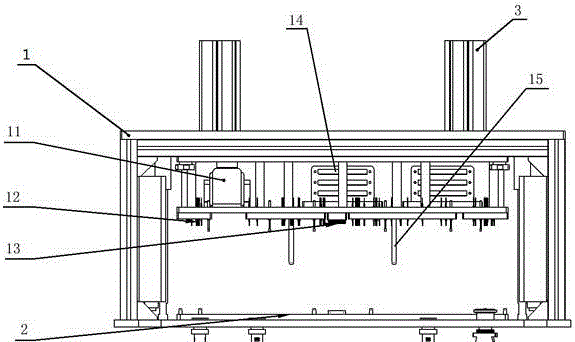
[0058] Embodiment one, such as figure 1 As shown, the LCD driver board automatic detection system includes:

[0059] Upper mold 1, lower mold 2, cylinder 3, industrial computer, image acquisition card, signal generation board, circuit board. The circuit main board is used to control the up and down movement of the cylinder 3, and is also used to process the sensor in-position signal, detect the voltage of the detected LCD driver board, communicate with the industrial computer, and process various external key trigger signals. The cylinder 3 is installed above the upper die 1 to drive the upper die 1 to lift or press down. The lower mold 2 is arranged below the upper mold 1 for fixing the LCD driver board to be tested. A code scanner 11 , a probe 12 , a microneedle 13 and a positioning pin 15 are installed on the bottom surface of the upper mold 1 . The probe 12 is connected with the image acquisition card, and the microneedle 13 is connected with the signal generating board...

Embodiment 2

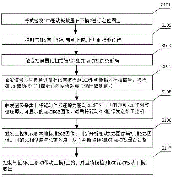
[0063] Embodiment 2, the method for automatic detection of LCD driver board, comprises steps:

[0064] Step S101, placing the LCD driver board to be tested on the lower mold 2 for positioning and fixing.

[0065] After the system is started, the transport device transports the detected LCD driver board to the lower mold 2, and positions and fixes the detected LCD driver board, so as to facilitate subsequent detection of the detected LCD driver board.

[0066] Step S102, controlling the cylinder 3 to move downward to drive the upper mold 1 to press down to the detection position.

[0067] The detection position is specifically the position corresponding to when the lower mold 1 is pressed down to the position where the positioning pin 15 and the lower mold 2 are just positioned.

[0068] The control cylinder 3 moves downward to drive the upper mold 1 to press down, and when receiving the in-position signal from the sensor, the control cylinder 3 stops moving down and stops at ...


PUM


Abstract

The invention provides an LCD driver board automatic detection method and system, and relates to the electronic field. The LCD driver board automatic detection system comprises an upper die, a lower die, cylinders, an industrial control computer, an image acquisition card, a signal generation plate and a circuit main board. The circuit main board is used for controlling the cylinders to move up and down; the cylinders are arranged above the upper die, and are used for driving the upper die to rise or fall; the lower die is arranged under the upper die, and is used for fixing an LCD driver board under detection; and the bottom surface of the upper die is equipped with a code scanner, probes, micropins and locating pins, wherein the code scanner is used for scanning a bar code of the LCD driver board under detection to help the system to identify the LCD driver board under detection, and the locating pins are used for realizing positioning with the position of the lower die in the pressing-down process of the upper die. The advantages are that the system and method are low in human cost, high in work efficiency, small in detection error and low in error rate; and a liquid crystal display screen is not easy to burn.

Description

technical field [0001] The invention relates to the field of electronics, in particular to an automatic detection method and system for an LCD driving board for performing mechanical automatic detection on the functions of the LCD driving board. Background technique [0002] LCD (abbreviation for Liquid Crystal Display) liquid crystal display is a flat display device, which consists of a certain number of color or black and white pixels, placed in front of the light source or reflective surface. Liquid crystal displays consume very little power, making them favored by engineers for electronic devices that run on batteries. Its main principle is to stimulate liquid crystal molecules with current to generate points, lines, and surfaces to form a picture with the back lamp tube. Opening the case of the LCD monitor reveals several circuit boards. Among them, a circuit board with a large area and a relatively compact design is the main board of the liquid crystal display, usual...

Claims


Application Information

Patent Timeline
Patent Type & Authority Applications(China)
IPC IPC(8): G09G3/00
CPCG09G3/006
Inventor 郭海范围李楚贤
Owner 深圳市海达唯赢科技有限公司
Why Eureka
Try Eureka