Humidifying system of air conditioner

A humidification system and air conditioning technology, applied in air humidification systems, heating and ventilation control systems, heating and ventilation safety systems, etc., can solve problems such as troublesome, suboptimal environment, and inability to cooperate well

Active Publication Date: 2016-09-14
NINGBO AUX ELECTRIC
View PDF8 Cites 13 Cited by
  • Summary
  • Abstract
  • Description
  • Claims
  • Application Information

AI Technical Summary

Problems solved by technology

[0002] At present, most families use wall-mounted air conditioners. When the air conditioner starts to heat in winter, the air in the house will become dry and make people feel uncomfortable. In order to meet the fogging height of the humidifier, the existing air conditioner humidifiers will If it is installed on the top of the humidifier, and the air conditioner humidifier is placed below the air outlet of the air conditioner, the hot air blown out from the air outlet of the air conditioner will mix with the mist sprayed from the mist outlet, the humidification effect is poor, and when the height of the installation space is in the direction of When limited, due to the fixed height of the air conditioner itself, there are strict requirements on the height of the humidifier itself, and the height of the humidifier itself determines the fogging height of the humidifier, and the fogging height determines the fogging effect of the humidifier. Some air conditioner humidifiers are difficult to install and have poor humidification effect; if the air conditioner humidifier is installed on the side of the air conditioner, and then the mist outlet pipe on the top of the humidifier is bent and then extended sideways into the air outlet of the air conditioner, the installation requirements will be reduced. Strict and troublesome, and installing the mist outlet directly on the side of the humidifier will reduce the fogging height of the humidifier, thereby reducing the working efficiency of the humidifier; in addition, the existing air conditioner and humidifier are two Independent individuals, the two cannot cooperate well, making the indoor environment less than optimal

Method used


Image

  • Humidifying system of air conditioner
  • Humidifying system of air conditioner
  • Humidifying system of air conditioner

Examples


Embodiment Construction

[0014] The present invention will be further described below in conjunction with the drawings.

[0015] In the description of the present invention, it should be understood that the terms "upper", "lower", "inner", "outer" and other indicating orientations or positional relations are based on the positional relations described in the drawings, and are only for the convenience of describing the present invention. Or simplify the description instead of indicating the specific orientation that must be possessed.

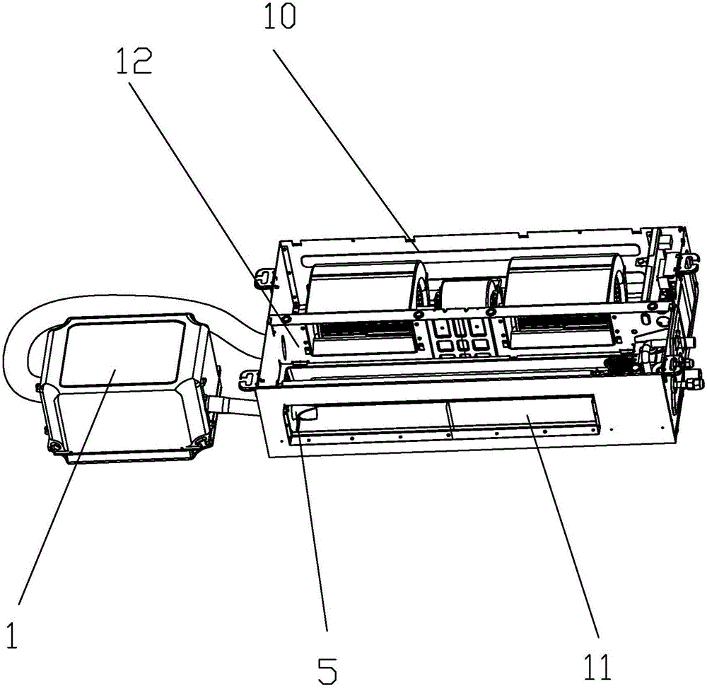
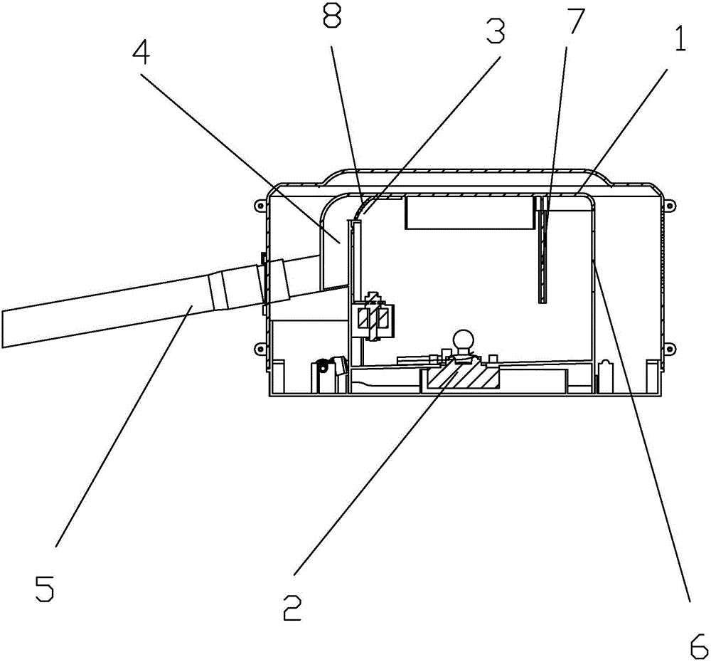
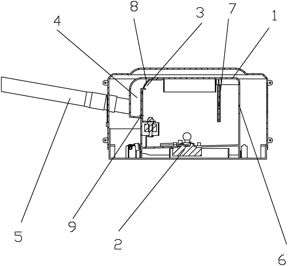
[0016] Such as Figure 1 to Figure 3 As shown, an air-conditioning humidification system includes a duct machine 10 and a humidifier body 1. The duct machine 10 is provided with main air separated by a heat exchanger into an air outlet 11 and a high static pressure air supply cavity 12 The humidifier body 1 is provided with an atomizer 2 at the bottom, and a mist outlet opening 3 is provided on the top of a side wall of the humidifier body 1. The mist outlet opening 3 and t...


PUM


Abstract

A humidifying system of an air conditioner comprises a ducted type air conditioner (10) and a humidifier body (1), wherein a main air duct, which is divided into an air outlet (11) and a high static pressure air supplying chamber (12) through a heat exchanger, is arranged on the ducted type air conditioner (10); an atomizer (2) is arranged at the bottom part of the humidifier body (1); a mist venting opening (3), which communicates with a mist venting chamber (4) at the outside of the sidewall of the humidifier body (1), is formed in the top part of one sidewall of the humidifier body (1); a mist venting tube (5), which can laterally extend into the air outlet of the ducted type air conditioner (10), is fixedly connected to the outer sidewall of the mist venting chamber body (4); an air supplying port (6), which communicates with the high static pressure air supplying chamber (12) through a pipeline, is formed in the upper part of the outer wall of one side, far away from the mist venting opening (3), of the humidifier body (1).

Description

Technical field [0001] The invention relates to an air conditioning humidification system. Background technique [0002] At present, most households use wall-mounted air conditioners. When the air conditioner starts heating in winter, the air inside the house becomes dry and makes people feel uncomfortable. The existing air conditioner humidifiers all have fog outlets to meet the fog height of the humidifier. It is installed on the top of the humidifier and the humidifier of the air conditioner is located below the air outlet of the air conditioner. The hot air blows from the air outlet of the air conditioner and mixes with the water mist sprayed from the mist outlet. The humidification effect is poor, and when the height of the installation space is When restricted, due to the fixed height of the air conditioner, it has strict requirements on the height of the humidifier itself, and the height of the humidifier itself determines the fogging height of the humidifier, and the fogg...

Claims


Application Information

Patent Timeline
Patent Type & Authority Applications(China)
IPC IPC(8): F24F6/12F24F13/22F24F11/00
CPCF24F6/12F24F11/30F24F13/222F24F2110/20
Inventor 李实学蒋建军王继承
Owner NINGBO AUX ELECTRIC
Why Eureka
Try Eureka