Powered device and system for urban track traffic

A technology of urban rail transit and power receiving devices, applied in the direction of driving rail devices, power rails, collectors, etc., can solve potential safety hazards, affect urban landscape and safety, electric shock and other problems, and achieve the effect of ensuring safety

Inactive Publication Date: 2016-09-21
CRRC DALIAN R & D CO LTD
View PDF5 Cites 16 Cited by
  • Summary
  • Abstract
  • Description
  • Claims
  • Application Information

AI Technical Summary

Problems solved by technology

[0005] The purpose of the present invention is to provide a power receiving device and system for urban rail transit, which is used to solve the problem of affecting urban landscape and safety in the way of erecting the power supply catenary throughout the whole process of the prior art, for example, erecting high-voltage catenary at key intersections , the height of passing vehicles is limited. When some vehicles transport materials, it is easy to scratch the catenary, resulting in electric shock, and there are certain safety hazards.

Method used


Image

  • Powered device and system for urban track traffic
  • Powered device and system for urban track traffic
  • Powered device and system for urban track traffic

Examples


Embodiment 1

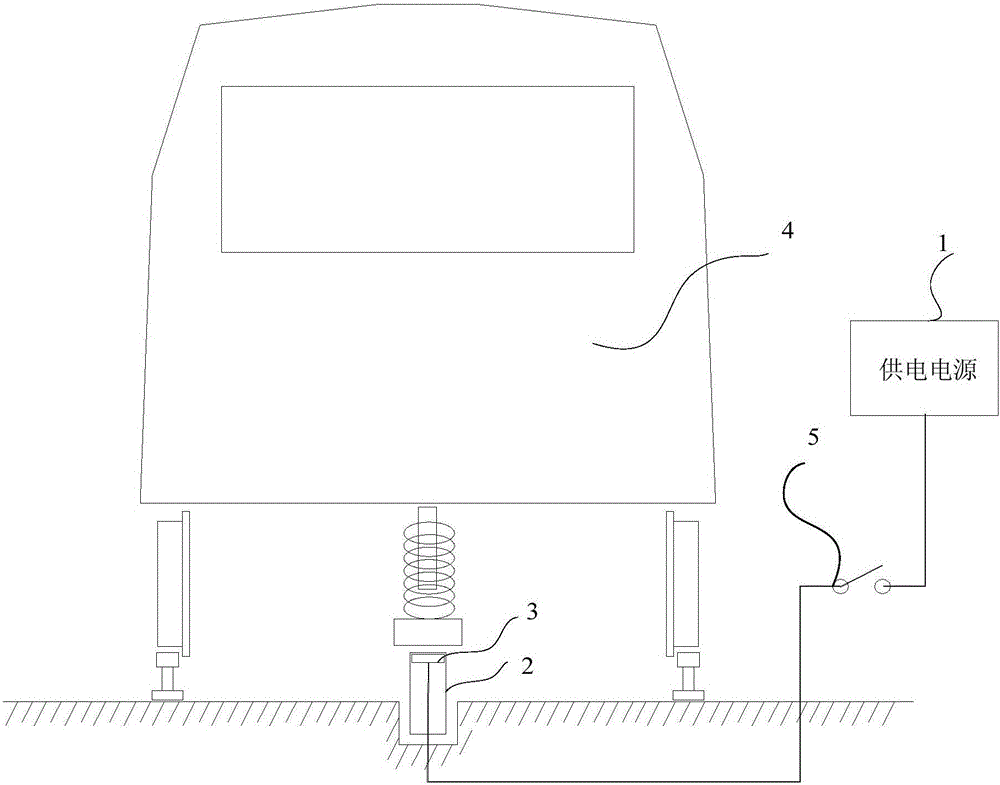
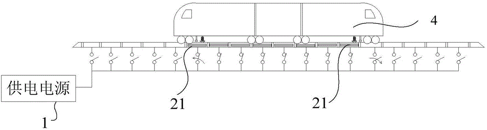
[0027] figure 2 It is a schematic structural diagram of an urban rail transit power receiving device provided in Embodiment 1 of the present invention, image 3 It is a schematic diagram of the stop state of the train station provided by Embodiment 1 of the present invention. Such as figure 2 and image 3 As shown, the urban rail transit power receiving device provided in this embodiment includes: a power supply 1, a power supply rail 2 and a transponder 3, wherein the power supply 1 is electrically connected to the power supply rail 2, and the power supply rail 2 includes a plurality of mutually insulated power supply The electronic track 21 and the transponder 3 are electrically connected to each power supply track 21 for receiving the control signal sent by the train 4 to control the conduction between the power supply track 21 under the train 4 and the power supply 1 to supply power to the train 4 .

[0028] Specifically, the transponder 3 includes any one or more of ...

Embodiment 2

[0033] On the basis of the first embodiment, this embodiment specifically explains how the transponder controls the conduction of the power supply sub-track under the train. Figure 4 It is a schematic diagram of the running state of the train entering the station provided by Embodiment 2 of the present invention, Figure 5 It is a schematic diagram of the running state of the train out of the station provided by Embodiment 2 of the present invention. in, Figure 4 and Figure 5 The arrows in represent the direction of travel of the train.

[0034] The transponder 3 is specifically used to receive the closing signal sent by the train 4 to control the conduction state between the power supply sub-track 21 and the power supply 1 that the front wheels of the train 4 pass, and is also used to receive the disconnect signal sent by the train to control Disconnect between the power supply sub-track 21 and the power supply that the train 4 rear wheels pass through.

[0035] Option...

Embodiment 3

[0046] An urban rail transit power receiving system provided in this embodiment, Figure 6 The structural diagram of the urban traffic power receiving system provided for the third embodiment of the present invention, as Figure 6 As shown, the system includes: an urban rail transit power receiving device and a train 4, and the train 4 includes: a transmitter 42 and an energy storage device 41 for storing electric energy for driving the train. Wherein, the transmitter 42 is used to send a control signal to the transponder 3 to control the conduction between the power supply sub-track 21 under the train 6 and the power supply 1 to supply power to the energy storage device 41 .

[0047] Wherein, the urban rail transit power receiving device provided in this embodiment may be the power receiving device in Embodiment 1 and Embodiment 2.

[0048] Specifically, the transmitter 42 includes any one or more of a magnetic sensor, a radio coupling device, and a radio frequency identific...


PUM


Abstract

The invention discloses a powered device and system for urban track traffic. The device comprises a power supply, a power supply track connected with the power supply and a transponder. The power supply track comprises multiple power supply sub-tracks insulated from one another. The transponder is electrically connected with all the power supply sub-tracks and used for receiving control signals sent by a train to control connection between the power supply sub-tracks below the train and the power supply so as to supply power to the train. In the powered device and system for urban track traffic, when the train passes, the power supply sub-tracks below the train are controlled to be connected; due to the fact that all the power supply sub-tracks are insulated from one another, it can be guaranteed that no electrified part exists on the periphery of the train, and the safety of the powered device and system is guaranteed.

Description

technical field [0001] The invention relates to the technical field of rail transit power supply, in particular to an urban rail transit power receiving device and system. Background technique [0002] Urban rail transit mainly refers to urban subway, urban express rail, light rail, tram, etc. Urban rail transit generally requires continuous power supply from the power system to ensure its normal operation. [0003] In the prior art, urban rail transit generally adopts a continuous power receiving method, and the overhead catenary is used to continuously provide electric energy for trains. figure 1 A structural schematic diagram of catenary power supply in the prior art, such as figure 1 As shown, in the prior art, a continuous power supply catenary 14 needs to be erected throughout the whole process above the train 12, and a pantograph 13 is installed on the roof of the train 12, and continuous power is received through the contact between the pantograph 13 and the catena...

Claims


Application Information

Patent Timeline
Patent Type & Authority Applications(China)
IPC IPC(8): B60M1/30B60M7/00B60L5/00
CPCB60M1/30B60L5/00B60M7/003
Inventor 车向中郭建斌姜涛马晨普
Owner CRRC DALIAN R & D CO LTD
Why Eureka
Try Eureka