An all-electronic asymmetric high-voltage pulse track circuit system and its application method
A high-voltage pulse, track circuit technology, applied in the field of rail transit, can solve the problems of equipment lack of fault monitoring, single function, adding pulse signal receivers, etc.
- Summary
- Abstract
- Description
- Claims
- Application Information
AI Technical Summary
Problems solved by technology
Method used
Image
Examples
Embodiment 1
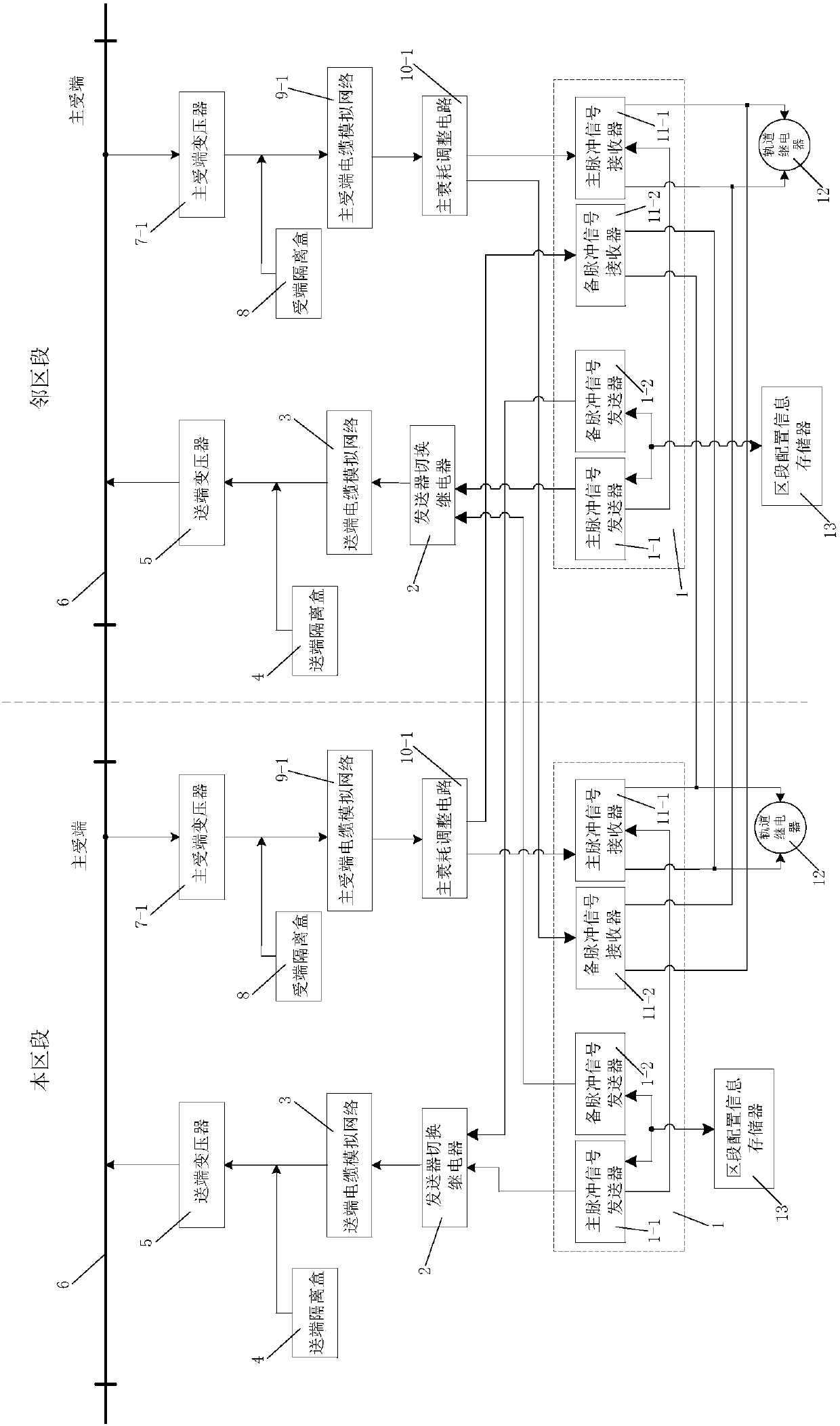
[0072] like figure 1 As shown, the all-electronic asymmetric high-voltage pulse track circuit system of this embodiment includes a sending-end device, a receiving-end device, an integrated sending and receiving control module 1, and an area for storing configuration information of this section and adjacent sections. Segment configuration information memory 13; the sending and receiving integrated control module 1 includes a main pulse signal transmitter 1-1, a main pulse signal receiver 11-1, a backup pulse signal transmitter 1-2 and a backup pulse signal receiver 11- 2. The section configuration information memory 13 is connected to the main pulse signal transmitter 1-1 and the standby pulse signal transmitter 1-2; the sending-end equipment includes a transmitter switching relay 2, a sending-end cable simulation network 3 and The sending end transformer 5, the main pulse signal transmitter 1-1 of this section is connected with the input end of the sending end cable simulation...
Embodiment 2
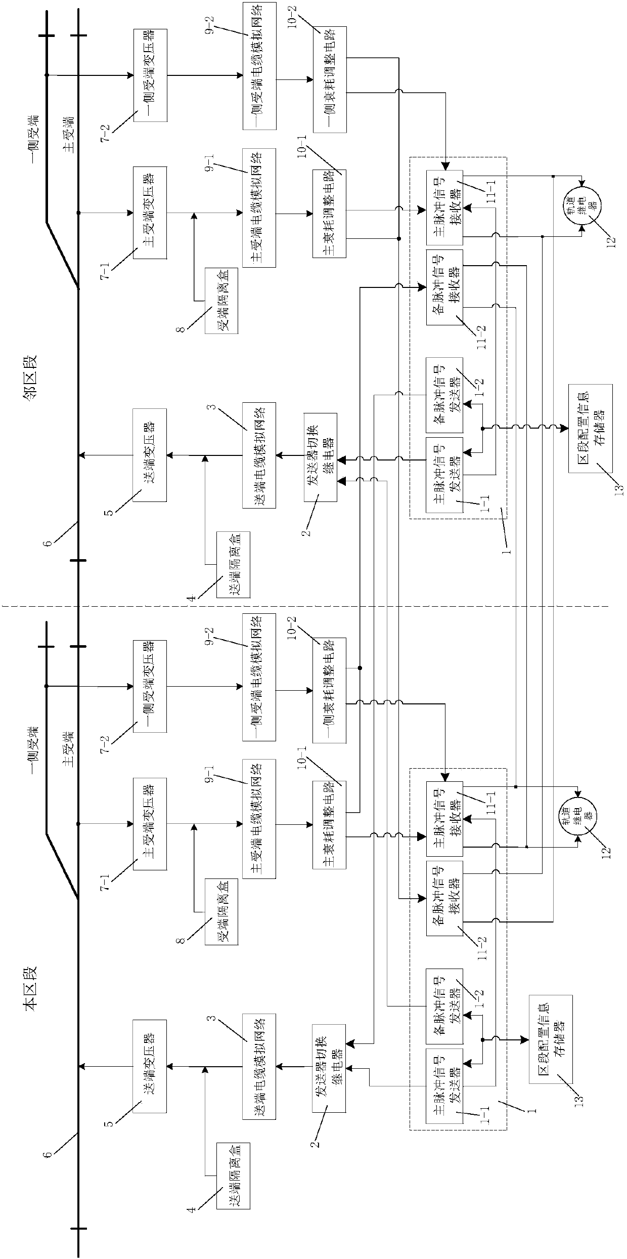
[0102] Such as figure 2As shown, the all-electronic asymmetric high-voltage pulse track circuit system of this embodiment is different from Embodiment 1 in that: the number of the receiving end transmission adjustment equipment is two, and they are respectively the main receiving end transmission adjustment equipment and one side main Receiving-end transmission adjustment equipment, correspondingly, the number of receiving-end transformers is two and respectively the main receiving-end transformer 7-1 and one-side receiving-end transformer 7-2, and the number of receiving-end cable simulation networks is two and The main receiving end cable simulation network 9-1 and one side receiving end cable simulation network 9-2 respectively, the number of the attenuation adjustment circuits is two and respectively the main attenuation adjustment circuit 10-1 and one side attenuation adjustment circuit 10-1 Adjustment circuit 10-2; the input end of the main pulse signal receiver 11-1 in...
Embodiment 3
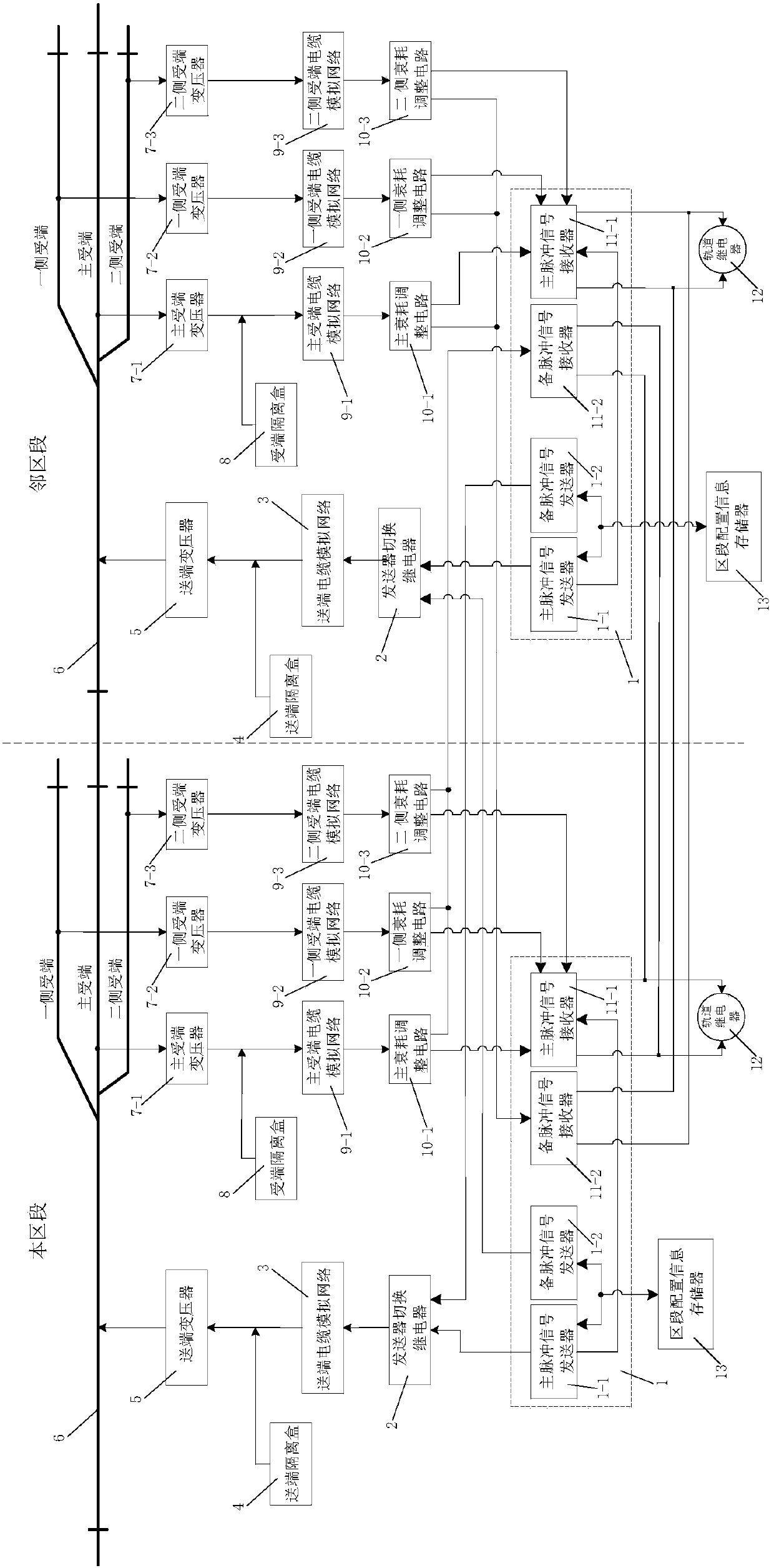
[0107] like image 3 As shown, the difference between this embodiment and Embodiment 1 is that the number of receiving end transmission adjustment devices is three, and they are respectively the main receiving end transmission adjustment device, one side main receiving end transmission adjustment device, and two side main receiving end transmission adjustment devices. Transmission adjustment equipment, correspondingly, the number of the receiving end transformers is three and are respectively the main receiving end transformer 7-1, one side receiving end transformer 7-2 and two side receiving end transformers 7-3, and the receiving end cable simulates The number of networks is three and they are respectively the main receiving end cable simulation network 9-1, one side receiving end cable simulation network 9-2 and two sides receiving end cable simulation network 9-3, and the number of the attenuation adjustment circuits is Three main attenuation adjustment circuits 10-1, one-...
PUM
 Abstract
Description
Claims
Application Information
 - R&D
- Intellectual Property
- Life Sciences
- Materials
- Tech Scout
- Unparalleled Data Quality
- Higher Quality Content
- 60% Fewer Hallucinations
Browse by: Latest US Patents, China's latest patents, Technical Efficacy Thesaurus, Application Domain, Technology Topic, Popular Technical Reports.
© 2025 PatSnap. All rights reserved.Legal|Privacy policy|Modern Slavery Act Transparency Statement|Sitemap|About US| Contact US: help@patsnap.com


