Conveying device

A transmission device and transmission unit technology, applied in the field of machinery, can solve the problems of large-area contact, poor control of transmission speed, increase in factory equipment procurement costs and maintenance costs, etc.

Inactive Publication Date: 2016-09-21
BOE TECH GRP CO LTD +1
View PDF4 Cites 2 Cited by
  • Summary
  • Abstract
  • Description
  • Claims
  • Application Information

AI Technical Summary

Problems solved by technology

However, in the substrate transfer device in the prior art, the rollers are inevitably in contact with the glass substrate in a large area during the transfer process of the substrate, and the glass substrate is easily damaged during the transfer process, resulting in poor production; The speed is not easy to control; in addition, the number of rollers is too large, which increases the cost of factory equipment procurement and maintenance costs, etc., and large-scale contact, especially for glass substrates with back patterns, the regional and possibility of scratches are high. certain risk

Method used


Image

  • Conveying device
  • Conveying device
  • Conveying device

Examples


Embodiment Construction

[0032] In order to make the purpose, technical solutions and advantages of the embodiments of the present invention more clear, the following will clearly and completely describe the technical solutions of the embodiments of the present invention in conjunction with the drawings of the embodiments of the present invention. Apparently, the described embodiments are some, not all, embodiments of the present invention. All other embodiments obtained by those skilled in the art based on the described embodiments of the present invention belong to the protection scope of the present invention.

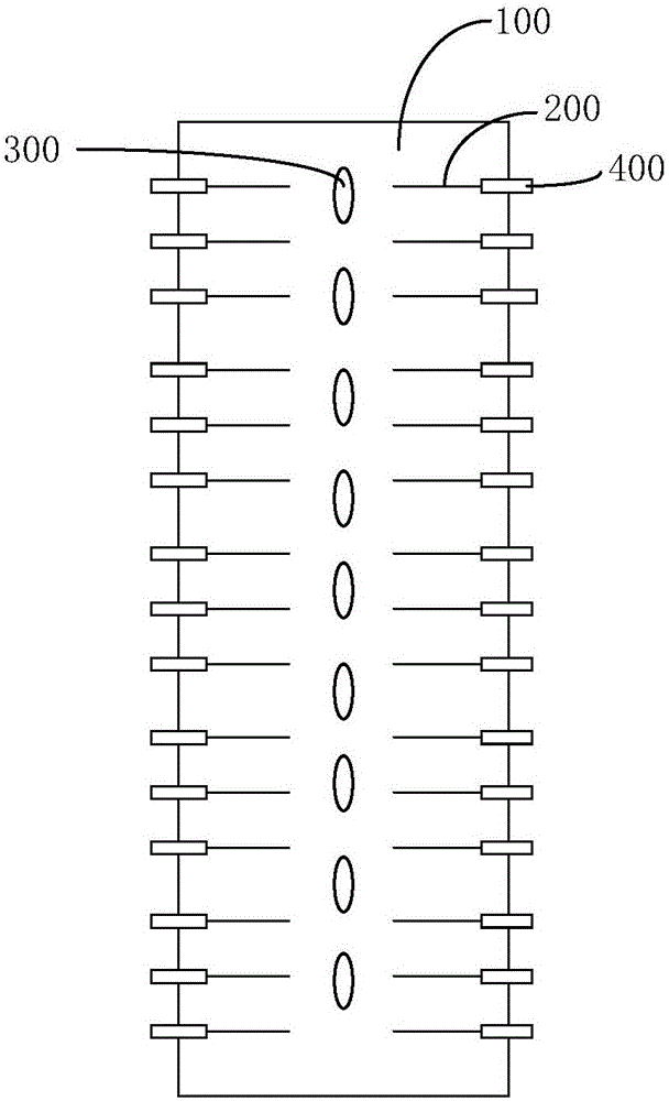
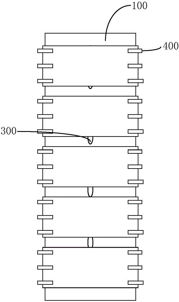
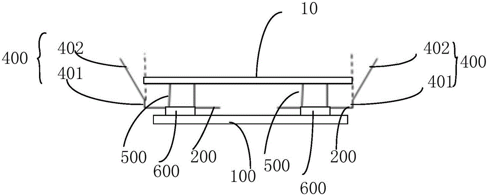
[0033] Aiming at the problems in the prior art that the objects to be conveyed are easily damaged due to the use of rollers to convey the objects to be conveyed, and the transmission speed is not easy to control, the present invention provides a conveying device that can reduce the number of objects to be conveyed (such as glass substrates) The contact with the conveying device during the c...


PUM


Abstract

The invention provides a conveying device. The conveying device comprises a conveying body support, a supporting unit used for supporting a to-be-conveyed object and conveying units. The supporting unit comprises a plurality of supporting rods used for being supported on the two opposite sides of the to-be-conveyed object. The conveying units are arranged on the conveying body support and connected with the supporting unit and can move on the conveying body support to drive the supporting unit to move so that the to-be-conveyed object can be conveyed. The conveying units are arranged on the two sides of the conveying body support and are used for supporting and conveying the to-be-conveyed object. Compared with the prior art, contact between the to-be-conveyed object and the conveying device in the conveying process is reduced, the breakage rate in the carrying process is reduced, and the production yield is increased. When to-be-conveyed objects with patterns on the back side are encountered, the locality and possibility of scratching of the back side patterns can be greatly reduced, the quality is guaranteed, and the conveying speed is more easily controlled. Compared with a traditional conveying device, the number of wheels is reduced, and the equipment purchasing and installing and maintaining cost is saved.

Description

technical field [0001] The invention relates to the field of mechanical technology, in particular to a transmission device. Background technique [0002] In the prior art, the conveying device generally adopts the way of roller conveying. Taking the TFT-LCD (ThinFilm Transistor-Liquid Crystal Display) manufacturing field as an example, the glass substrate is passed from one process to another through a substrate conveying device. During the conveying process, the glass substrate is carried on the rollers. Through the rotation of the rollers, the glass substrate and the rollers generate relative motion, which drives the glass substrate to move along the horizontal plane. However, in the substrate transfer device in the prior art, the rollers are inevitably in contact with the glass substrate in a large area during the transfer process of the substrate, and the glass substrate is easily damaged during the transfer process, resulting in poor production; The speed is not easy ...

Claims


Application Information

Patent Timeline
Patent Type & Authority Applications(China)
IPC IPC(8): B65G49/06
CPCB65G49/063
Inventor 吴春晖余世荣孟庆勇杨涛蒋盛超
Owner BOE TECH GRP CO LTD
Why Eureka
Try Eureka