Slidable supporting device used for optical fiber preform cutting apparatus

A technology of optical fiber preform and sliding support, applied in glass cutting devices, glass manufacturing equipment, manufacturing tools, etc., can solve the problems of uneven section, easy expansion, and cracks on the cutting surface, so as to ensure the quality of the cutting section and avoid section cracks , to avoid the effect of brittle fracture

Active Publication Date: 2016-09-21
TONGDING INTERCONNECTION INFORMATION CO LTD +1
View PDF5 Cites 2 Cited by
  • Summary
  • Abstract
  • Description
  • Claims
  • Application Information

AI Technical Summary

Problems solved by technology

[0005] The existing problems in the cutting process of the preform are mainly that the cutting section is prone to brittle fracture, the section is uneven, the flatness is not high, and cracks appear around the cutting surface. After analysis, it is found that the main reason for this phenomenon is: prefabricated During the cutting process of the rod, the 6 degrees of freedom in space are not completely restricted, and there is always a degree of freedom in the horizontal plane and a degree of freedom in the direction of movement. In this way, when the cutting force is applied, the preform will inevitably move and rotate. It itself is a brittle material, and tiny cracks are easy to expand, resulting in a series of cutting defects

Method used


Image

  • Slidable supporting device used for optical fiber preform cutting apparatus
  • Slidable supporting device used for optical fiber preform cutting apparatus
  • Slidable supporting device used for optical fiber preform cutting apparatus

Examples


Embodiment Construction

[0029] It should be noted that, in the case of no conflict, the embodiments of the present invention and the features in the embodiments can be combined with each other.

[0030] In describing the present invention, it should be understood that the terms "center", "longitudinal", "transverse", "upper", "lower", "front", "rear", "left", "right", The orientations or positional relationships indicated by "vertical", "horizontal", "top", "bottom", "inner", "outer", etc. are based on the orientation or positional relationships shown in the drawings, and are only for the convenience of describing the present invention Creation and simplification of description, rather than indicating or implying that the device or element referred to must have a specific orientation, be constructed and operate in a specific orientation, and therefore should not be construed as limiting the invention. In addition, the terms "first", "second", etc. are used for descriptive purposes only, and should no...


PUM


Abstract

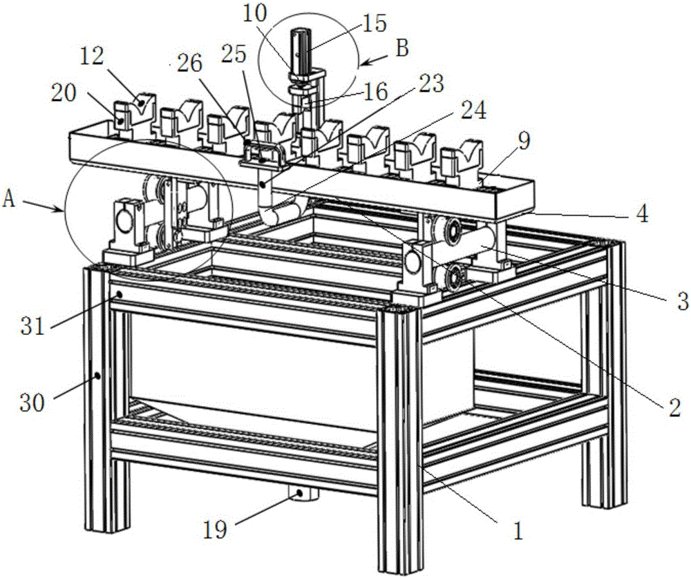
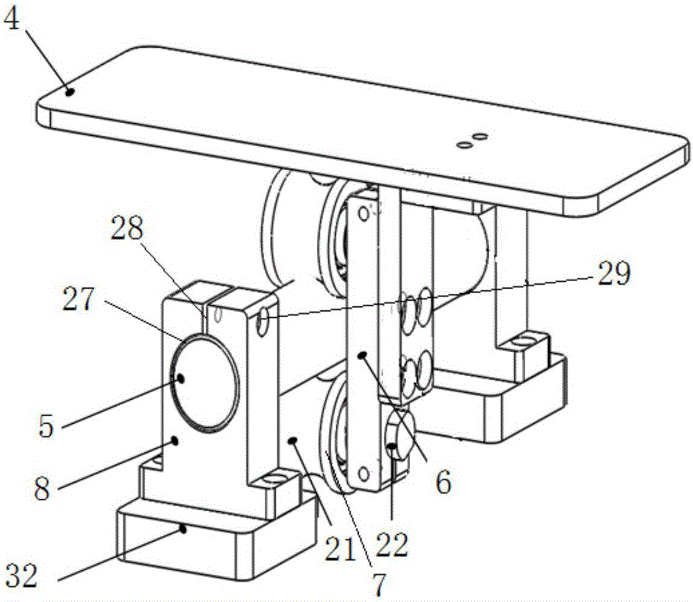
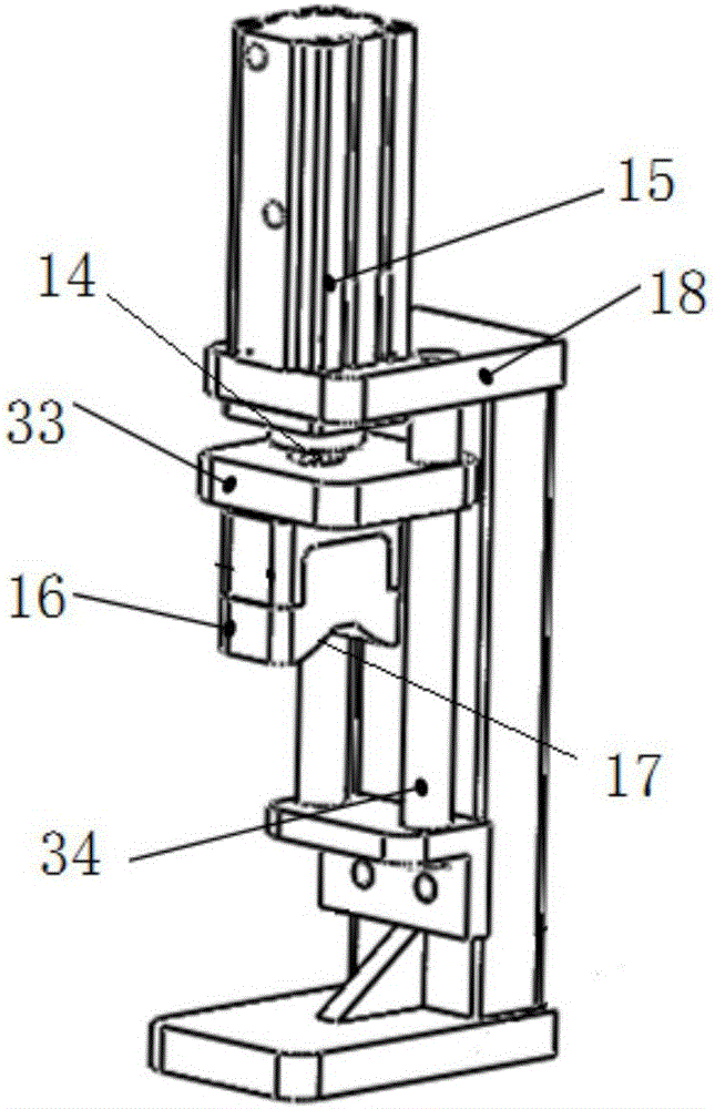
The invention provides a slidable supporting device used for an optical fiber preform cutting apparatus. The slidable supporting device comprises a frame, a positioning mechanism and sliding mechanisms mounted on the frame, wherein the positioning mechanism is mounted on a slidable supporting platform, and the sliding mechanisms are symmetrically arranged at the left and right ends of the slidable supporting platform; each sliding mechanism comprises a guide rail and two positioning rollers arranged on a same roller support; the guide rail is mounted on the frame through a guide rail supporting seat; two positioning rollers are arranged above and below the guide rail in a correspondence way and are slidable on the guide rail along an axial direction; the slidable supporting platform is mounted on the upper end of the roller support; and the positioning mechanism comprises a supporting assembly and a compressing assembly. According to the invention, the slidable supporting platform can steadily and smoothly move back and forth along the guide rail, so the quality of a cutting section is guaranteed; and through starting of a cylinder, the compressing assembly is driven to compress a an optical fiber preform, six degrees of freedom of the space of the compressing assembly are confined, so movement or rotation of the preform caused by cutting force during cutting is avoided.

Description

technical field [0001] The invention belongs to the technical field of optical fiber preform manufacturing and research and development, and in particular relates to a sliding support device for optical fiber preform cutting equipment. Background technique [0002] Optical fiber preform is the core raw material for manufacturing quartz series optical fibers. The glass special prefabricated rod used for drawing optical fiber (filament) is mainly divided into four types: OVD (out-of-rod chemical vapor deposition method), VAD (axial vapor phase deposition method), MCVD (modified chemical vapor deposition method), and MCVD (modified chemical vapor deposition method). phase deposition method), PCVD (plasma activated chemical vapor deposition method), the research and development and manufacture of these optical fiber preform production equipment are mainly concentrated in the United States and Japan, and domestic optical fiber manufacturers have gradually begun to increase the re...

Claims


Application Information

Patent Timeline
IPC IPC(8): C03B33/06C03B37/012
CPCC03B33/06C03B37/012
Inventor 沈小平王祥蒋小强满小忠向德成张峰伟
Owner TONGDING INTERCONNECTION INFORMATION CO LTD
Why Eureka
Try Eureka