Force reflecting haptic interface

a haptic interface and force-reflecting technology, applied in the field of man/machine interfaces, to achieve the effect of prolonging or prolonging the use of the haptic interface, enhancing user safety and comfor

Inactive Publication Date: 2006-01-10
3D SYST INC
View PDF196 Cites 122 Cited by
  • Summary
  • Abstract
  • Description
  • Claims
  • Application Information

AI Technical Summary

Benefits of technology

[0008]Three actuators and cable drives are utilized in the interface to power the first, second, and third rotary axes. Each of the cable drives includes at least one automatic cable tensioning device for preventing backlash and a grounded or ungrounded actuator capstan to prevent slippage of each cable relative to its respective actuator capstan. Cable drives on the first and second axes include cables manufactured from a braided tungsten or polymer composition including a fused blend of high modulus polyethylene fibers and liquid crystal aromatic polyester-polyarylate fibers which exhibit low creep, high strength, and long life. The third axis drive includes a braided tungsten or polymer composition cable to drive a transfer element and first and second metal cables driven by the transfer element to power the third axis. Each metal cable has a centrally disposed aluminum or stainless steel rod, or other suitably rigid member, and looped stranded stainless steel or braided tungsten cable ends. In combination, the components of the third axis drive provide high stiffness and prevent backlash in a remotely actuated, cantilevered drive.
[0009]The actuator for the third articulation is disposed remotely, proximate the actuator for the second articulation in the hub thereof, to minimize the size and the weight of the third articulation. Accordingly, the second articulation hub is configured with two hubs nested on a common axis, namely the second axis.

Problems solved by technology

Significant challenges exist in designing a force reflecting haptic interface with appropriate operational and response characteristics.

Method used


Image

  • Force reflecting haptic interface
  • Force reflecting haptic interface
  • Force reflecting haptic interface

Examples


Embodiment Construction

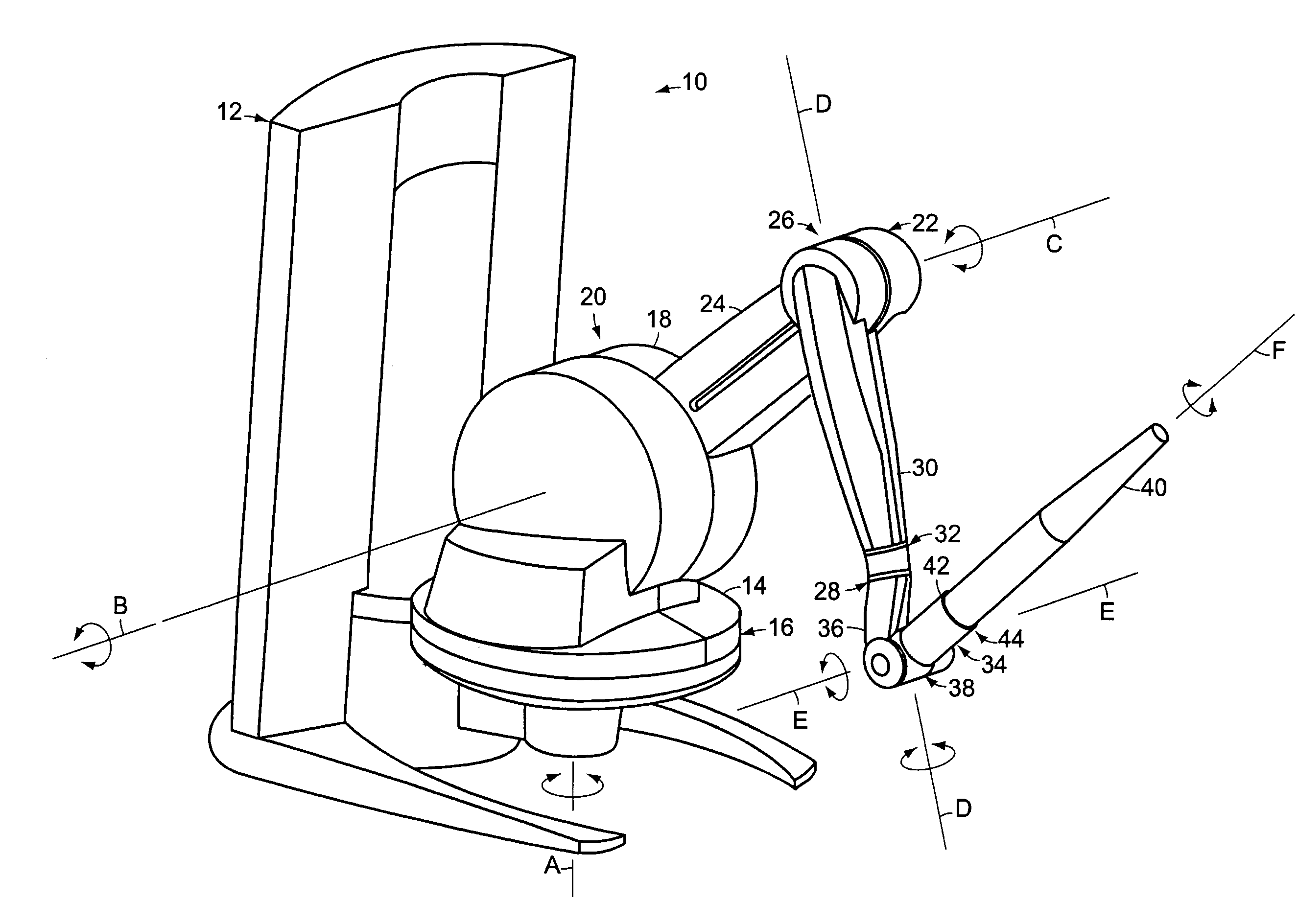
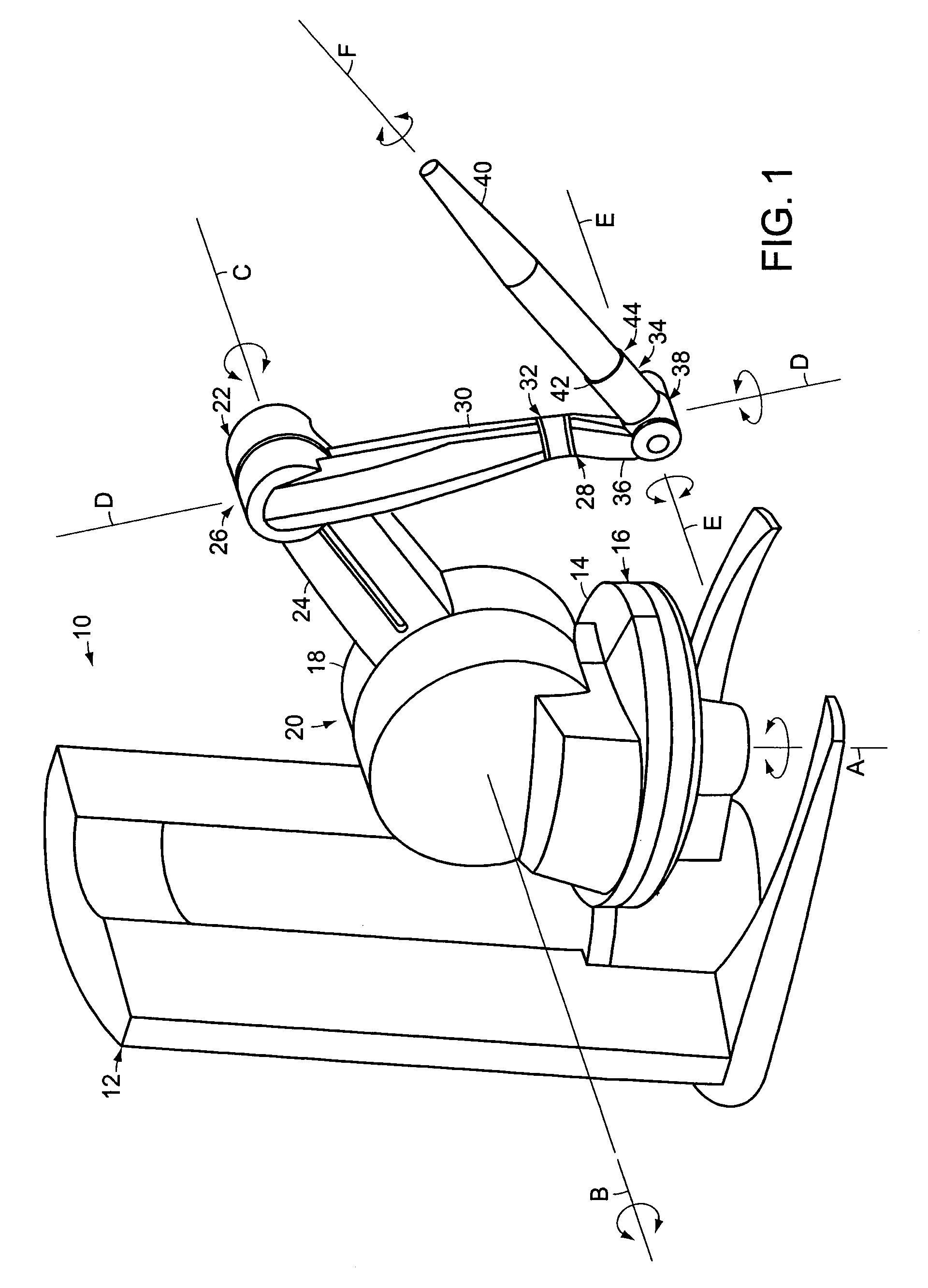
[0031]FIG. 1 is a schematic perspective view of a six degree of freedom force reflecting haptic interface 10 in accordance with one embodiment of the present invention. The interface 10 includes a housing 12 defining a reference ground, six joints or articulations, and six structural elements. A first powered tracked rotary element 14 is supported by the housing 12 to define a first articulation 16 with an axis “A” having a substantially vertical orientation. A second powered tracked rotary element 18 is mounted thereon to define a second articulation 20 with an axis “B” having a substantially perpendicular orientation relative to the first axis, A. A third powered tracked rotary element 22 is mounted on a generally outwardly radially disposed extension 24 of the second element 18 to define a third articulation 26 having an axis “C” which is substantially parallel to the second axis, B. A fourth free rotary element 28 is mounted on a generally outwardly radially disposed extension 3...


PUM


Abstract

A six degree of freedom force reflecting haptic interface includes three powered axes and three free axes, all of which are tracked so that the position of a user connection element in the work volume can be determined. The interface includes cable drives with polymer composite or metallic cables, automatic cable tensioning devices, and grounded actuator capstans. A nested hub and transfer drive provide a compact, weight balanced interface. User comfort and safety features are also provided.

Description

CROSS-REFERENCE TO RELATED APPLICATION[0001]This application claims priority to U.S. provisional patent application Ser. No. 60 / 093,300 filed on Jul. 17, 1998, the disclosure of which is incorporated herein by reference in its entirety. This application also incorporates herein by reference a U.S. patent application filed of even date herewith and is identified by Ser. No. 09 / 356,119.TECHNICAL FIELD[0002]The present invention relates generally to a man / machine interface and, more specifically, to a force reflecting haptic interface.BACKGROUND[0003]Force reflecting haptic interfaces and associated computer hardware and software are used in a variety of systems to provide tactile sensory feedback to a user in addition to conventional visual feedback, thereby affording an enhanced man / machine interface. These systems are becoming more prevalent in such diverse areas as surgical technique training, industrial design and modeling, and personal entertainment.[0004]An example of a haptic i...

Claims


Application Information

Patent Timeline
Patent Type & Authority Patents(United States)
IPC IPC(8): G09G5/00
CPCG06F3/016
Inventor RODOMISTA, GUYZIEGLER, ANDREWGOODWIN, WILLIAM A.BOLTON, CLIVEMASSIE, THOMAS H.LOHSE, R. MICHAEL
Owner 3D SYST INC
Why Eureka
Try Eureka