Self-moving temporary support device beside gob-side entry retaining

A temporary support and self-moving technology, which is applied in mine roof support, mining equipment, earthwork drilling and mining, etc., can solve the problems that the support cannot be too long, the overall rigidity is small, and cannot be adapted, so as to protect the safety of operators and support Good stability, good blocking effect

Active Publication Date: 2018-07-03
SHAANXI PIONEERING ARCHITECTURAL TECH
View PDF5 Cites 0 Cited by
  • Summary
  • Abstract
  • Description
  • Claims
  • Application Information

AI Technical Summary

Problems solved by technology

[0003] First, there is no hinge connection between the front and rear frames, and the overall rigidity is small, which is not conducive to stability; second, there is no horizontal oil cylinder connection between the two rows of supports, and the stability is weak; third, it cannot adapt to the mutual inversion of the left and right working surfaces , that is, it cannot adapt to the situation that the goaf is on the left side of the support direction. Fourth, the support should not be too long, otherwise it will be difficult to go down the well, and the small size is not suitable for the technical requirements of 15-20 meters of daily mining. It needs to be studied A roadway retaining support that can satisfy underground transportation and cannot be transported down the mine due to its large size; at the same time, it has the function of blocking gangue and effectively supports the roof; it has good stability; the depth of entering the goaf is small; Retreat and adapt to the left and right working faces for gob-side entry retention

Method used


Image

  • Self-moving temporary support device beside gob-side entry retaining
  • Self-moving temporary support device beside gob-side entry retaining
  • Self-moving temporary support device beside gob-side entry retaining

Examples


Embodiment Construction

[0026] The present invention will be described in detail below in conjunction with the accompanying drawings and specific embodiments.

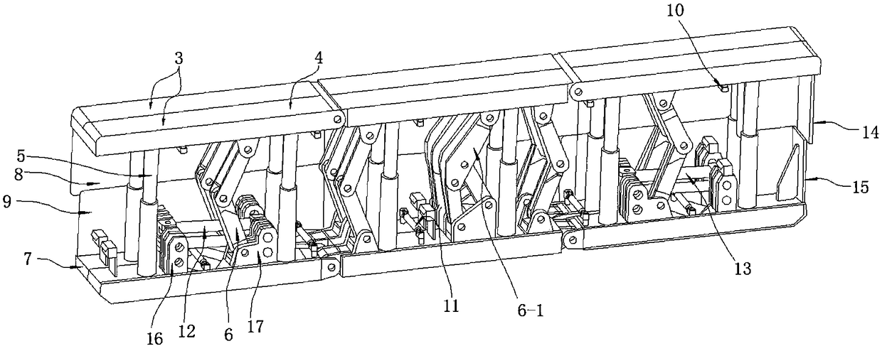
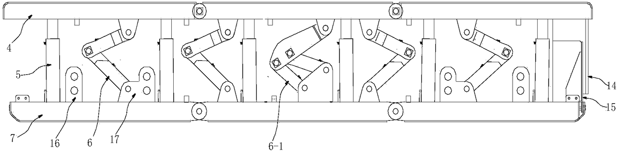
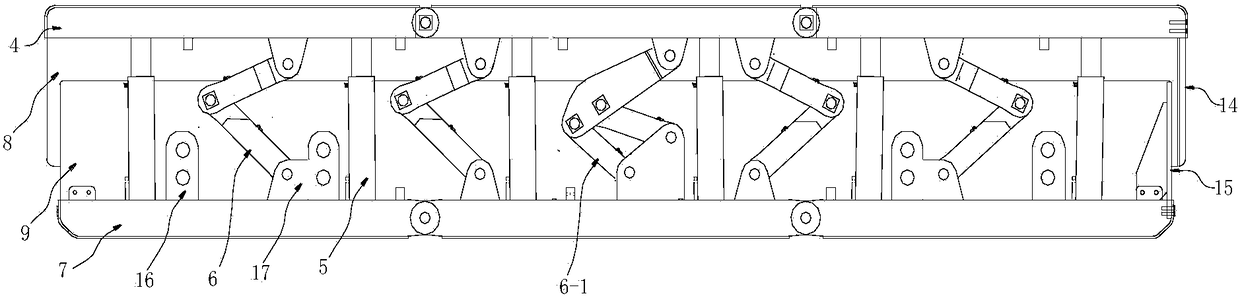
[0027] The invention provides a self-moving temporary support device beside the gob-side entry retaining, such as Figure 1 to Figure 5 As shown, the self-moving temporary support device beside the gob-side entry retaining includes an electro-hydraulic control system, and is characterized in that it includes two rows of support bodies connected side by side by oil cylinders, and the first row of support bodies 1 is close to the gob-side entryway 20 On one side, the second row of support bodies 2 is close to the side of the gob. Each row of support bodies includes three support units 3 connected in sequence. Each support unit 3 includes a top beam 4, and the top beam 4 passes through a hydraulic column 5 and a single pendulum The rod 6 is connected to the base 7, wherein the second row of bracket units 3 of each row of bracket bodies is provid...


PUM


Abstract

The invention discloses a self-moving temporary support device beside gob-side entry retaining. The device comprises two rows of side-by-side support bodies connected by oil cylinders, the first row of support body is close to the gob-side entry retaining side, and the second row of support body is close to the gob area side, each row of support body comprises 1-5 support unit connected in order, and each support unit consists of a top beam, a hydraulic column, a single wobbling rod and a pedestal, the top beam is connected to the pedestal through the hydraulic column and single wobbling rod, wherein each row of support body at least has 1 support unit equipped with four-bar linkage; the second row of support body is provided with gangue blocking plates close to the gob area side; the tails of the two rows of support bodies are equipped with gangue blocking plates; and horizontal push-pull oil cylinders and longitudinal push-pull oil cylinders are disposed between the two rows of support bodies. The device provided by the invention solves the problem of mechanical safe gangue blocking in the gob area of gob-side entry retaining, at the same time greatly improves the entry retaining speed from a current daily entry retaining of 10m to 15-20m, is in line with the high yield and high efficiency requirements of coal mines, and can be widely applied in coal mining, metallurgy and other industries.

Description

technical field [0001] The invention belongs to the technical field of coal mine mining without coal pillars, and relates to a self-moving temporary support device beside a gob-side roadway. Background technique [0002] At present, there are two forms of coal pillar-free mining in my country: gob-side entry retention and gob-side entry entry. Gobside entry retention is representative of flexible mold concrete gobside entry retention technology, which generally uses wooden point columns to resist the gangue falling from the goaf, creating space for construction workers to work and pour walls. In coal seams above 3 meters When implementing gob-side entry retention, the cost of wooden point columns is high, the construction is difficult, and the amount of work is large. Moreover, wooden point columns cannot effectively block gangue and are easy to fall, endangering the personal safety of operators. The relevant patents I applied for earlier have the following problems: [00...

Claims


Application Information

Patent Timeline
Patent Type & Authority Patents(China)
IPC IPC(8): E21D23/03E21D23/04E21D23/14
CPCE21D23/0004E21D23/0052E21D23/03E21D23/04E21D23/14
Inventor 王晓利魏朝张智强吴玉意
Owner SHAANXI PIONEERING ARCHITECTURAL TECH
Why Eureka
Try Eureka