Medium-pressure high-speed rotating connector

A high-speed rotation, medium-pressure technology, applied in the direction of pipes/pipe joints/fittings, adjustable connections, passing components, etc., can solve the problems of frequent replacement, joint damage, waste of material and financial resources, etc.

Active Publication Date: 2016-09-21
TENGZHOU TIANXUAN ROTARY UNION
View PDF6 Cites 7 Cited by
  • Summary
  • Abstract
  • Description
  • Claims
  • Application Information

AI Technical Summary

Problems solved by technology

[0002] In pneumatic and hydraulic equipment and CNC machining centers, there is often a need to transport media to high-speed rotating equipment. However, due to the limited speed of the current rotary j

Method used


Image

  • Medium-pressure high-speed rotating connector

Examples


Embodiment Construction

[0020] The principles and features of the present invention are described below in conjunction with the accompanying drawings, and the examples given are only used to explain the present invention, and are not intended to limit the scope of the present invention.

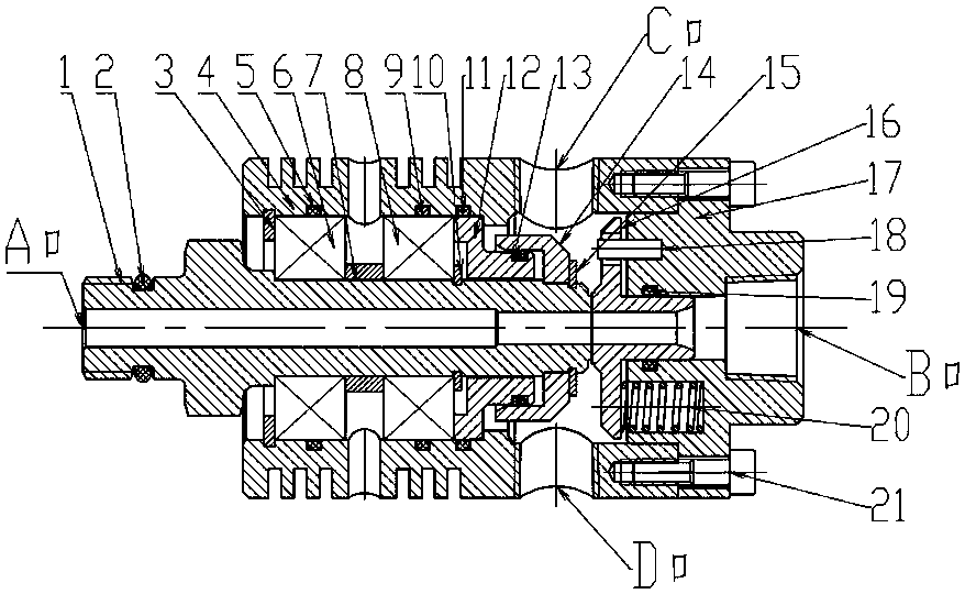
[0021] Such as figure 1 As shown, a medium-pressure high-speed rotary joint includes a housing 4, one end of the housing 4 is fixedly connected with an end cover 17, and a static sealing ring 16 is connected to the inner side of the end cover 17 with a clearance fit, and a rotating joint is connected with the relative rotation in the housing 4. Shaft 1, the inner end surface of the rotating shaft 1 and the inner end surface of the static sealing ring 16 are in airtight contact and communicated, the inner wall of the housing 4 is connected with a sealing spacer 12, the rotating shaft 1 passes through the middle of the sealing spacer 12, and the sealing spacer 12 faces The side where the static sealing ring 16 is loca...


PUM


Abstract

The invention discloses a medium-pressure high-speed rotating connector. The medium-pressure high-speed rotating connector comprises a shell body; an end cover is fixedly connected to one end of the shell body, and a stationary sealing ring is connected to the inner side of the end cover in a clearance fit mode; a rotating shaft is connected in the shell body in a relative rotation mode, and a sealing spacer bush is connected to the inner wall of the shell body; the rotating shaft penetrates through the middle of the sealing spacer bush, and a boss is machined on the side, facing the stationary sealing ring, of the sealing spacer bush; the side surface of the boss is provided with an annular groove, piston rings are movably connected into the annular groove; a sealing sleeve is fixedly connected to the part, between the sealing spacer bush and the inner end surface of the rotating shaft, of the outside of the rotating shaft; a groove body is formed in the position, on the side surface of the sealing spacer bush, of the sealing sleeve; the sealing sleeve inner side wall where the groove is located makes fixed contact with the outer diameters of the piston rings in a sealed mode; the piston rings form a labyrinth seal between the sealing sleeve and the sealing spacer bush; the outer wall of the shell body is provided with two threaded connection openings which are located at the sealed contact surface of the inner end surface of the rotating shaft and the inner end surface of the stationary sealing ring.

Description

technical field [0001] The invention relates to a rotary joint, in particular to a medium-pressure high-speed rotary joint. Background technique [0002] In pneumatic and hydraulic equipment and CNC machining centers, there is often a need to transport media to high-speed rotating equipment. However, due to the limited speed of the current rotary joints, the use of such rotary joints cannot meet the requirements of the working conditions, resulting in damage to the joints Serious, frequent replacement, and a waste of material and financial resources. Contents of the invention [0003] The present invention aims at the deficiencies of the above-mentioned prior art, and provides a medium-pressure high-speed rotary joint, which can be applied to high-speed rotating conditions and meet the requirement of conveying medium to high-speed rotating equipment. [0004] The technical scheme that the present invention solves the problems of the technologies described above is as foll...

Claims


Application Information

Patent Timeline
IPC IPC(8): F16L27/08
CPCF16L27/0828
Inventor 盖延峰邵明秋何士芬
Owner TENGZHOU TIANXUAN ROTARY UNION
Why Eureka
Try Eureka