Low-gravity-center spherical cloud platform locking structure

A locking structure, low center of gravity technology, applied in the field of gimbal, can solve the problems of affecting normal work, instability, inconvenience in use and carrying, etc., and achieve the effect of being conducive to mass production, stable locking effect, and convenient to use and carry

Active Publication Date: 2016-09-21
广东徕图影像科技有限公司
View PDF6 Cites 2 Cited by
  • Summary
  • Abstract
  • Description
  • Claims
  • Application Information

AI Technical Summary

Problems solved by technology

[0002] At present, the existing photographic tripods on the market are equipped with spherical heads to adjust the angle of the quick mount; however, the existing spherical heads are directly supported and locked on the ball seat by the locking rod on the outside of the ball seat The universal ball inside is used to achieve locking, the locking effect is extremely poor, extremely unstable, and it is easy to cause damage to the surface of the universal ball, affecting normal work, and the axial height is relatively high, not only high cost, but also relatively bulky, occupying a lot of space , inconvenient to use and carry

Method used


Image

  • Low-gravity-center spherical cloud platform locking structure
  • Low-gravity-center spherical cloud platform locking structure

Examples


Embodiment Construction

[0018] In order to make the object, technical solution and advantages of the present invention clearer, the present invention will be further described in detail below in conjunction with the accompanying drawings and embodiments. It should be understood that the specific embodiments described here are only used to explain the present invention, not to limit the present invention.

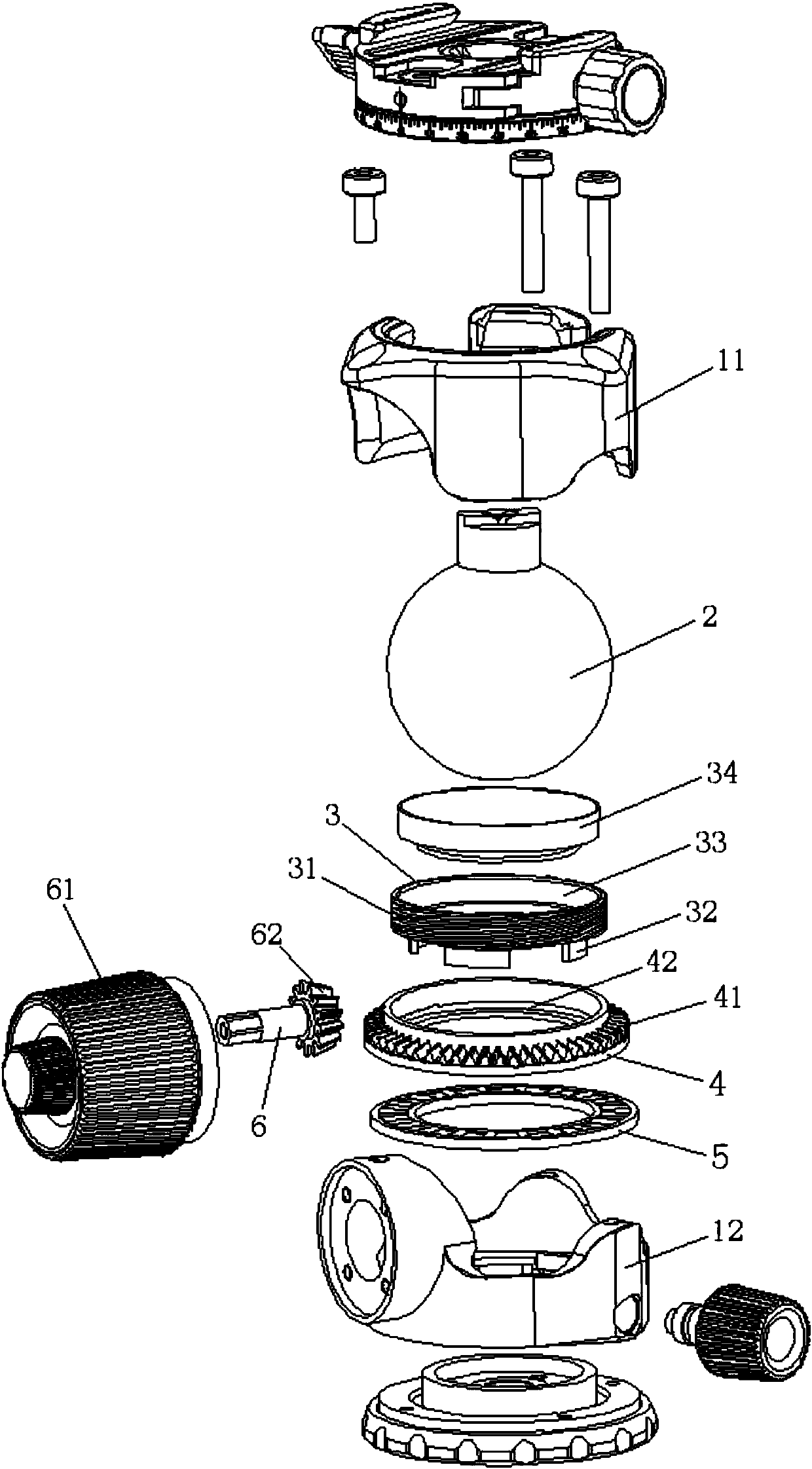
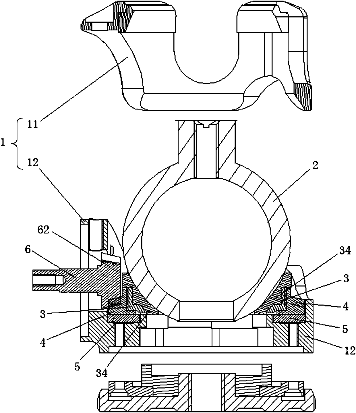
[0019] Such as figure 1 with figure 2 as shown in:

[0020] The embodiment of the present invention provides a low-center-of-gravity spherical pan / tilt locking structure, including a cylinder 1, a sphere 2, a locking seat 3, a bevel gear rotating seat 4, a bearing 5 and a locking drive rod 6, and the sphere 2 , locking seat 3, bevel gear rotating seat 4 and bearing 5 are all located in the locking chamber 13 provided by cylinder body 1. Wherein, the bearing 5 can be an annular thrust bearing, which is located at the bottom of the locking cavity 13; the bevel gear rotating seat 4 is an annular c...


PUM


Abstract

The invention provides a low-gravity-center spherical cloud platform locking structure. The locking structure comprises a barrel body, a ball body, a locking seat, a conical gear rotating seat, a bearing and a locking driving rod, and the ball body, the locking seat, the conical gear rotating seat and the bearing are all arranged in a locking cavity of the barrel body; the bearing is arranged at the bottom of the locking cavity; the conical gear rotating seat is rotatably mounted on the bearing, the conical outer surface of the conical gear rotating seat is provided with teeth, and the side wall of an inner ring is provided with an inner thread; a rotary knob is arranged at one end of the locking driving rod, the other end of the locking driving rod passes through the barrel body and extends into the locking cavity, the end of the locking driving rod is provided with a bevel gear, and the bevel gear is connected with the teeth of the conical gear rotating seat in an engaged manner; and the circumferential side surface of the locking seat is provided with an outer thread, the locking seat is arranged in the inner circular ring of the conical gear rotating seat, the outer thread is connected with the inner thread in a matched and engaged manner, and the locking seat moves up and down under the action of the conical gear rotating seat. The locking structure is stable and reliable in locking effect, ingenious and compact in structure, low in axial height and production cost, small in size and convenient to use and carry.

Description

【Technical field】 [0001] The invention belongs to the technical field of cloud platforms, and in particular relates to a locking structure of a spherical platform with a low center of gravity. 【Background technique】 [0002] At present, the existing photographic tripods on the market are equipped with spherical heads to adjust the angle of the quick mount; however, the existing spherical heads are directly supported and locked on the ball seat by the locking rod on the outside of the ball seat The universal ball inside is used to achieve locking, the locking effect is extremely poor, extremely unstable, and it is easy to cause damage to the surface of the universal ball, affecting normal work, and the axial height is relatively high, not only high cost, but also relatively bulky, occupying a lot of space , It is inconvenient to use and carry. 【Content of invention】 [0003] In order to solve the above-mentioned technical problems existing in the prior art, the present inv...

Claims


Application Information

Patent Timeline
Patent Type & Authority Applications(China)
IPC IPC(8): F16M11/14F16C11/10
CPCF16C11/106F16M11/14
Inventor 邓铜岭梅建云
Owner 广东徕图影像科技有限公司
Why Eureka
Try Eureka