Supercharge Your Innovation With Domain-Expert AI Agents!

A computer intelligent optical sight

An optical sight and computer technology, which is applied in the field of sight, can solve problems such as greater impact on accuracy, achieve visual inspection, reduce errors, and improve accuracy and efficiency.

Active Publication Date: 2018-02-23
李云琦
View PDF6 Cites 0 Cited by
  • Summary
  • Abstract
  • Description
  • Claims
  • Application Information

AI Technical Summary

Problems solved by technology

Since the image of the scope is enlarged and has divergent vignetting, it needs to be corrected by artificial vision, and the accuracy is greatly affected by human factors.

Method used


Image

  • A computer intelligent optical sight
  • A computer intelligent optical sight

Examples


Embodiment Construction

[0031] The principles and features of the present invention are described below in conjunction with the accompanying drawings, and the examples given are only used to explain the present invention, and are not intended to limit the scope of the present invention.

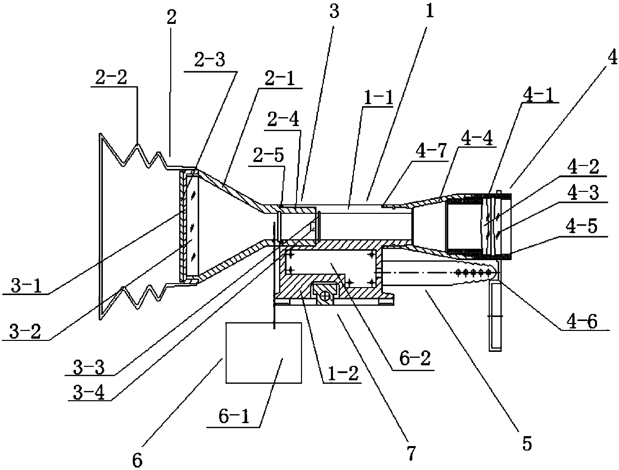
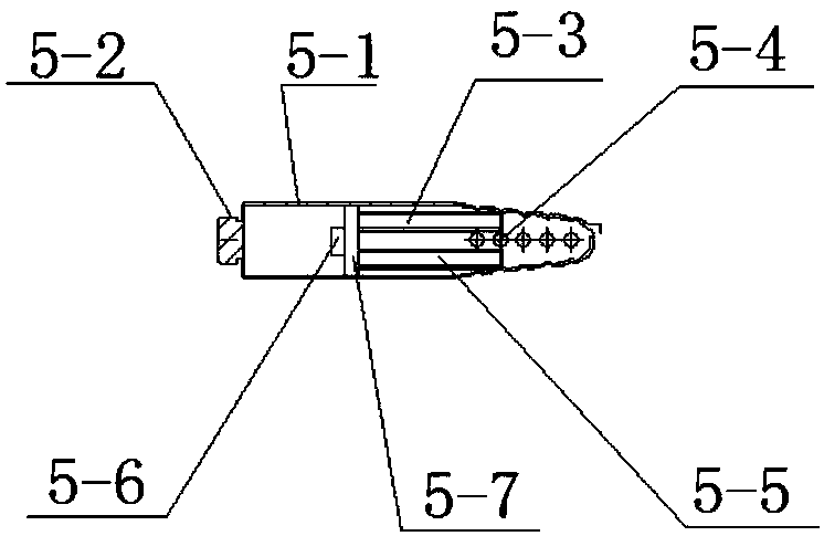
[0032] Such as figure 1 In the illustrated embodiment, the computer intelligent optical sight of the present invention includes a housing 1, an eyepiece imaging system 2, a CCD imaging processing system 3, an objective optical system 4, an anemometer measuring system 5, and a computer data processing system 6 And the frame coupling system7.

[0033] Wherein, the housing 1 includes a mirror body 1-1 and a base 1-2 fixedly arranged on the outer surface of the mirror body 1-1, one end of the mirror body 1-1 is connected to the eyepiece barrel 2-1, and the other end is connected to the objective lens Barrel 4-1 is connected.

[0034] The eyepiece imaging system 2 includes an eyepiece barrel 2-1, a hood 2-2, a hood pre...


PUM


Abstract

The invention discloses a computerized intelligent optical sight. The computerized intelligent optical sight comprises a shell, an eye lens imaging system, a CCD imaging processing system, an object lens optical system, an air speed tube measurement system, a computer data processing system and a gun body coupling system. The shell comprises a sight body and a base fixedly arranged on the outer surface of the sight body. The eye lens imaging system is arranged at one end of the sight body, and the CCD imaging processing system is arranged in the eye lens imaging system. The object lens optical system is arranged at the other end of the sight body. The air speed tube measurement system in parallel with the sight body is arranged at the end, close to the object lens optical system, of the base. The computer data processing system is fixedly arranged on the outer surface of the eye lens imaging system and is in communication connection with the CCD imaging processing system and the air speed tube measurement system. The gun body coupling system is arranged on the base. The computerized intelligent optical sight has the beneficial effects that distance measurement precision is improved; the influence of environmental factors on precision is reduced; shooting precision is improved; and the shooting distance is increased.

Description

technical field [0001] The invention relates to the field of sights, in particular to a computer intelligent optical sight. Background technique [0002] The 5.8mm sniper rifle scope currently used by the army is a white light optical system scope, and the existing defect is: the distance measurement is a comparative distance measurement, and the error is relatively large. Environmental factors such as air pressure, rain and snow, wind direction, and air volume have a great impact on the accuracy, and deviation correction needs to be done manually, and the deviation correction is not ideal when the environment is harsh. At zero time, there is only one calibration point for the gun and the scope, which needs to be corrected manually, and the ballistic impact point is corrected based on user experience. Since the image of the scope is magnified and shows divergent vignetting, it needs to be corrected by artificial vision, and the accuracy is greatly affected by human factors....

Claims


Application Information

Patent Timeline
Patent Type & Authority Patents(China)
IPC IPC(8): F41G1/46F41G1/473
CPCF41G1/46F41G1/473
Inventor 李云琦李卫平
Owner 李云琦
Features
  • R&D
  • Intellectual Property
  • Life Sciences
  • Materials
  • Tech Scout
  • Unparalleled Data Quality
  • Higher Quality Content
  • 60% Fewer Hallucinations
Learn More