Time-difference positioning method of radiation source with position error of passive detection observation station

A passive detection and time-difference positioning technology, applied in the field of communication, can solve the problems of unsatisfactory radiation source position estimation accuracy, unconsidered position error, and limited radiation source position estimation efficiency, etc., to improve estimation accuracy, overcome performance limitations, improve Estimated Efficiency Effects

Active Publication Date: 2018-04-17
XIDIAN UNIV
View PDF4 Cites 0 Cited by
  • Summary
  • Abstract
  • Description
  • Claims
  • Application Information

AI Technical Summary

Problems solved by technology

However, the disadvantage of this method is that due to the use of pseudo-linear equations that introduce auxiliary variables, additional steps are required to extract the radiation source position from the additional auxiliary variables, which limits the estimation efficiency of the radiation source position
In addition, because the position error existing in the movement of the passive detection observation station is not considered, the position estimation accuracy of the radiation source is not ideal when there is a position error in the passive detection observation station

Method used


Image

  • Time-difference positioning method of radiation source with position error of passive detection observation station
  • Time-difference positioning method of radiation source with position error of passive detection observation station
  • Time-difference positioning method of radiation source with position error of passive detection observation station

Examples


Embodiment Construction

[0032] The present invention will be further described below in conjunction with the accompanying drawings.

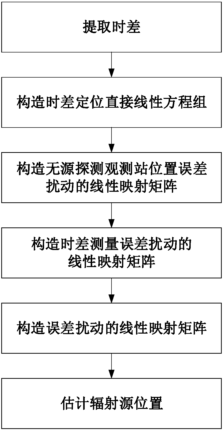
[0033] Refer to attached figure 1 , the concrete steps of the present invention are as follows.

[0034] Step 1, extract the time difference.

[0035] Each passive detection and observation station intercepts the signal transmitted by the radiation source, and measures the time when the signal transmitted by the radiation source reaches the respective position of the passive detection and observation station to obtain the arrival time.

[0036] Any one passive detection observation station receives the time when the signals propagated by the radiation source forwarded by other passive detection observation stations arrive at the respective positions of the passive detection observation station, and forms the arrival time vector.

[0037] Constructs the extraction matrix of the time difference vector.

[0038] The extraction matrix of the time difference vector is co...


PUM


Abstract

The invention discloses a radiation source time difference positioning method having a passive detection observation station position error. The radiation source time difference positioning method is characterized in that (1) a time difference is extracted; (2) a time difference positioning direct linear equation system is constructed; (3) a linear mapping matrix of a passive detection observation station position error disturbance is constructed; (4) a linear mapping matrix of a time difference measurement error disturbance is constructed; (5) a linear mapping matrix of an error disturbance is constructed; (6) a radiation source position is estimated. A time difference positioning direct linear model is adopted, and the position error of the passive detection observation station is considered, and the radiation source time difference positioning method is used for the radiation source passive positioning of the passive detection observation station.

Description

technical field [0001] The invention belongs to the technical field of communication, and further relates to time-difference positioning of a radiation source when there is a position error in a passive detection and observation station in the technical field of passive positioning. The invention can be used for passive positioning of radiation sources by motion platforms such as aircraft, satellites, and unmanned aerial vehicles. Background technique [0002] Passive localization of radiation sources is widely used in aircraft, satellites and drones, etc. The modern passive positioning system always places the passive detection observation station on the moving platform whose position is not known, which leads to the position error of the passive detection observation station. A small position error of the passive detection observation station will lead to a large error in the estimation of the position of the radiation source, so the method of estimating the position of t...

Claims


Application Information

Patent Timeline
Patent Type & Authority Patents(China)
IPC IPC(8): G01S5/16
CPCG01S5/16
Inventor 董春曦朱颖童董阳阳赵国庆饶鲜许锦唐峥钊刘明明
Owner XIDIAN UNIV
Why Eureka
Try Eureka