
Microscope longitudinally arranged lens adjustment support for medical mechanism

A technology for medical institutions and adjustable brackets, which is applied in microscopes, optics, instruments, etc., can solve the problems of troublesome installation and disassembly of lens adjustment devices and fixed brackets, single function of adjustment brackets, and limited adjustment range, etc., and achieves diversified control methods and improved adjustment Accuracy, simple and convenient loading and unloading effect

Inactive Publication Date: 2016-09-21
HUBEI XINYUAN TECH
View PDF0 Cites 2 Cited by
  • Summary
  • Abstract
  • Description
  • Claims
  • Application Information

AI Technical Summary

Problems solved by technology

[0003] The technical problem to be solved by the present invention is: in order to solve the problems existing in the above-mentioned background technology, provide an improved microscope vertical lens adjustment bracket for medical institutions, and solve the problem that the current adjustment bracket used for microscopes has a single function and a fixed structure. The magnification effect of the microscope can be adjusted by rotating the lower lens. This adjustment method is simple, the adjustment range is limited, the control method is also very single, and the space is occupied. It is very troublesome to install and disassemble between the lens adjustment device and the fixed bracket.

Method used


Image

  • Microscope longitudinally arranged lens adjustment support for medical mechanism
  • Microscope longitudinally arranged lens adjustment support for medical mechanism

Examples


Embodiment Construction

[0013] The present invention is described in further detail now in conjunction with accompanying drawing. These drawings are all simplified schematic diagrams, which only illustrate the basic structure of the present invention in a schematic manner, so they only show the configurations related to the present invention.

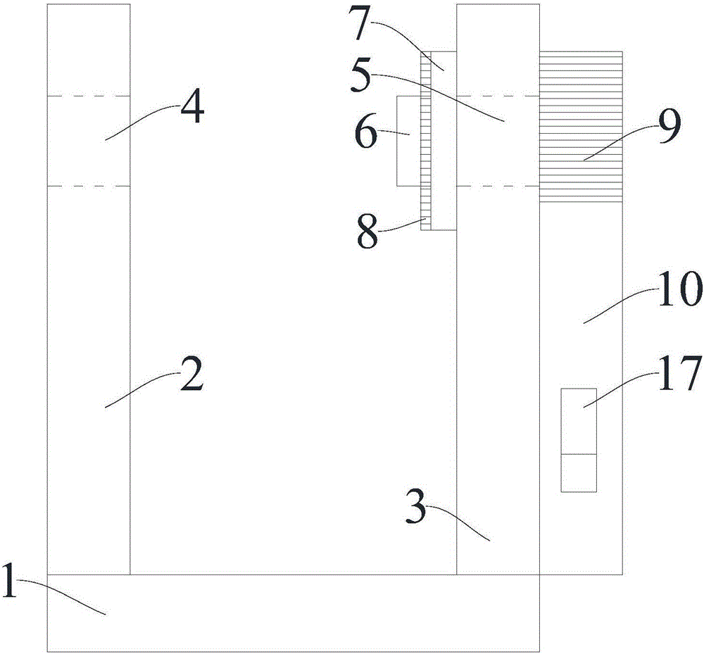
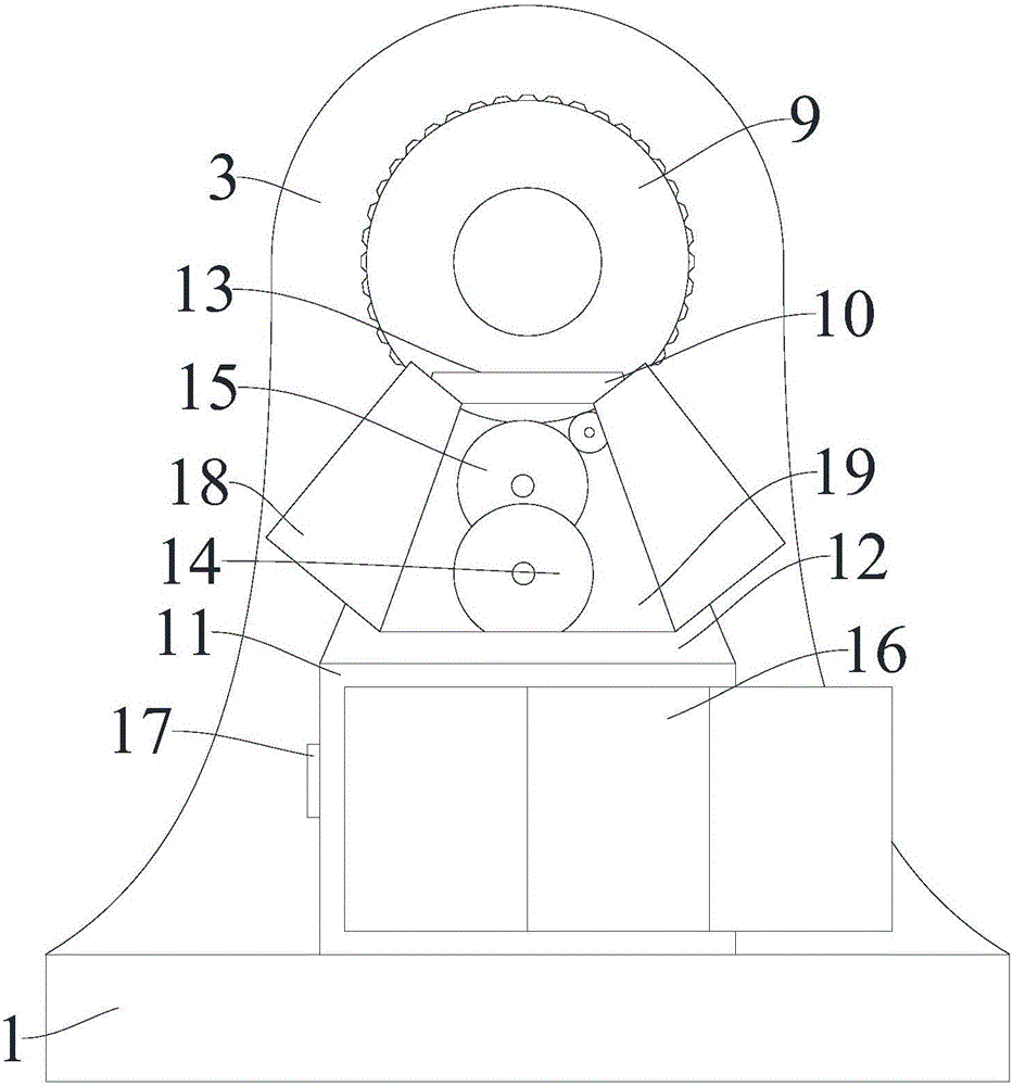
[0014] figure 1 with figure 2 A medical institution shown a microscope longitudinal lens adjustment bracket, comprising a base plate 1, the upper end of the base plate 1 is fixedly connected with a left longitudinal support plate 2 and a right longitudinal support plate 3, the upper ends of the left longitudinal support plate 2 and the right longitudinal support plate 3 are both With arc-shaped protrusions, the left longitudinal support plate 2 is provided with a left connection through hole 4 inside, and the right longitudinal support plate 3 is provided with a right connection through hole 5 corresponding to the position of the left connection through hole...


PUM


Abstract

The invention relates to the technical field of a medical equipment assembly, and especially relates to a microscope longitudinally arranged lens adjustment support for a medical mechanism. The microscope longitudinally arranged lens adjustment support comprises a base plate, the upper end of the base is fixedly connected with a left longitudinal support plate and a right longitudinal support plate, the upper end of the left longitudinal support plate and the upper end of the right longitudinal support plate are each provided with an arc-shaped projection, the left longitudinal support plate is internally provided with a left connection through hole, and a right connection through hole is arranged at a position, opposite to the left connection through hole, inside the right longitudinal support plate. According to the microscope longitudinally arranged lens adjustment support for the medical mechanism, a hollow adjustment pipe with a built-in limiting sleeve and an externally arranged hand-operated rotation button is installed in the right connection through hole of the right longitudinal support plate, rotation of the hollow adjustment pipe can be quite conveniently controlled through an electric control adjustment box at the outer side of the longitudinal support plate, the adjustment precision is improved, the control mode is more diversified, mounting and dismounting are simpler and more convenient, the volume is smaller, the portability is higher, and the practicality is greatly improved.

Description

technical field [0001] The invention relates to the technical field of medical equipment components, in particular to a microscope vertical lens adjustment bracket for medical institutions. Background technique [0002] At present, most of the microscopes used in hospitals are the most common microscopes on the market. Not only are they simple in structure, single in function, but also fixed in structure. The magnification effect of the microscope can only be adjusted by rotating the lower lens. This adjustment method is simple and the adjustment range is limited. The control method is also very simple, and the space is relatively large, and it is very troublesome to assemble and disassemble between the lens adjustment device and the fixed bracket. Contents of the invention [0003] The technical problem to be solved by the present invention is: in order to solve the problems existing in the above-mentioned background technology, provide an improved microscope vertical len...

Claims


Application Information

Patent Timeline
Patent Type & Authority Applications(China)
IPC IPC(8): G02B21/02G02B21/26
CPCG02B21/02G02B21/26
Inventor 涂昌建张烨余冰
Owner HUBEI XINYUAN TECH
Learn More