Vehicle positioning system and underground vehicle positioning method

A vehicle positioning and vehicle technology, applied in the field of vehicle positioning, can solve problems such as difficult to meet vehicle positioning and precise positioning requirements, and achieve the effect of high-precision positioning

Inactive Publication Date: 2016-09-21
BEIJING YONGANXINTONG TECH CO LTD
View PDF11 Cites 15 Cited by
  • Summary
  • Abstract
  • Description
  • Claims
  • Application Information

AI Technical Summary

Problems solved by technology

However, the RFID positioning system can only achieve regional positioning, and cannot meet the precise positioning requirements required for underground traffic dispatching. Traffic dispatching based on uncertain positioning data will only bring more uncertainty. In the positioning, the specific method of the existing technology is to convert the personnel identification card in the personnel positioning system into a vehicle card for use, but this method is difficult to meet the needs of vehicle positioning

Method used


Image

  • Vehicle positioning system and underground vehicle positioning method
  • Vehicle positioning system and underground vehicle positioning method
  • Vehicle positioning system and underground vehicle positioning method

Examples


Embodiment 1

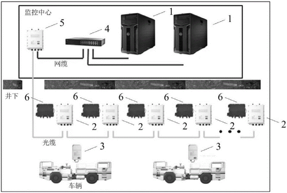
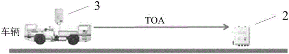
[0064] Embodiment one: if Image 6 As shown, if only one of the two directional antennas of the UWB anchor point 2 can receive the ranging signal, then the server 1 determines that the vehicle tracker 3 is located at the directional antenna of the UWB anchor point 2 that can receive the ranging signal. side;

[0065] In this embodiment, when the vehicle-mounted locator 3 is far away from the directional antenna, only the directional antenna facing the vehicle-mounted locator 3 can receive the ranging signal, and the back facing the directional antenna of the vehicle-mounted locator 3 cannot receive the distance measurement signal. Ranging signal, for example, assume that the front receiving distance of the directional antenna is 500 meters, and the back receiving distance is 100 meters. When the distance to the directional antenna of the vehicle-mounted locator 3 is greater than 100 meters, the server 1 can determine that the vehicle-mounted locator 3 is located on the side o...

Embodiment 2

[0066] Embodiment two: if Figure 7 As shown, if both directional antennas of UWB anchor point 2 can receive ranging signals, and the distance difference between the vehicle locator 3 and the two directional antennas is equal to the distance between the two directional antennas, then the server 1 determines that the vehicle positioning The device 3 is located on one side of the directional antenna that is closer to the distance;

[0067] In this embodiment, when the vehicle-mounted locator 3 is relatively close to the directional antenna, both directional antennas can receive ranging signals. For example, in the assumption of Embodiment 1, when the vehicle-mounted locator 3 is facing the vehicle When the distance between the directional antenna of the locator 3 and the directional antenna facing the vehicle-mounted locator 3 is less than 100 meters, then since the two directional antennas keep a distance of more than 1 meter, and the positioning accuracy of the UWB anchor poin...

Embodiment 3

[0068] Embodiment three: as Figure 8 As shown, if the two directional antennas of the UWB anchor point 2 can receive ranging signals, and the distance between the vehicle locator 3 and the two directional antennas is equal to the distance between the two directional antennas, then the server 1 determines that the vehicle positioning The device 3 is located between two directional antennas.


PUM


Abstract

The present invention discloses a vehicle positioning system and an underground vehicle positioning method, and belongs to the vehicle positioning field. The vehicle positioning system comprises a server, at least one UWB anchor point and a vehicle-mounted positioner capable of communicating with the UWB anchor point wirelessly, wherein the server is used to set a monitoring center above a well, the UWB anchor points is arranged under the well, and the UWB anchor points are connected in series; the vehicle-mounted positioner is set on an underground to-be-positioned vehicle, and one UWB anchor point is connected with the server via a switch of the monitoring center above the well. Compared with the prior art, and according to the present invention, the underground vehicle high-precision positioning can be realized.

Description

technical field [0001] The invention relates to the field of vehicle positioning, in particular to a vehicle positioning system and an underground vehicle positioning method. Background technique [0002] The trackless rubber-tyred vehicle is a vehicle that uses rubber wheels or crawlers as the traveling mechanism and uses explosion-proof diesel engines and batteries as the traction power to realize the transportation of materials, equipment and personnel. The trackless rubber-tyred vehicle auxiliary transportation is different from the traditional rail mine car, endless rope, small hoist relay transportation and other methods. Trackless rubber-tyred vehicles have no track restrictions, are flexible, adaptable, safe and efficient, and have a wide range of applications. They have been rapidly popularized and applied in recent years. Trackless rubber wheel transportation greatly reduces the labor intensity of workers and improves production efficiency; it simplifies auxiliary...

Claims


Application Information

Patent Timeline
Patent Type & Authority Applications(China)
IPC IPC(8): G08G1/123G01S5/02
CPCG08G1/123G01S5/02
Inventor 陈善辉
Owner BEIJING YONGANXINTONG TECH CO LTD
Why Eureka
Try Eureka