Relay zero-cross detection method and device and relay zero-cross calibration method and device

A zero-crossing detection and relay technology, applied in the direction of protection against overcurrent, can solve problems such as damage, avoid inrush current, improve circuit accuracy, and reduce production costs

Active Publication Date: 2016-09-21
QINGDAO HAIER INTELLIGENT HOME TECH CO LTD
View PDF6 Cites 9 Cited by
  • Summary
  • Abstract
  • Description
  • Claims
  • Application Information

AI Technical Summary

Problems solved by technology

[0004] The technical problem to be solved by the present invention is to provide a relay zero-crossing detection and calibration method and device to solve the problem in the prior art that when the relay is turned on, it is easily damaged by the surge current

Method used


Image

  • Relay zero-cross detection method and device and relay zero-cross calibration method and device
  • Relay zero-cross detection method and device and relay zero-cross calibration method and device
  • Relay zero-cross detection method and device and relay zero-cross calibration method and device

Examples


Embodiment 1

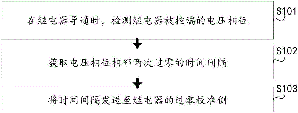
[0047] An embodiment of the present invention provides a relay zero-crossing detection method for the zero-crossing detection side, see figure 1 , including the following steps:

[0048] Step 101, when the relay is turned on, detect the voltage phase of the controlled terminal of the relay;

[0049] In this step, the zero-crossing detection side detects the voltage at both ends of the controlled terminal (that is, the output terminal) of the relay, which can effectively avoid errors caused by the delay of the relay itself. Therefore, by detecting the voltage phase of the controlled terminal of the relay, it is not necessary to consider the delay of the relay itself, and only need to obtain the voltage of the output terminal of the relay.

[0050] Step 102, acquiring the time interval between two adjacent zero crossings of the voltage phase.

[0051] In this step, when obtaining the zero-crossing time interval, first when receiving the relay on-off control command (that is, w...

Embodiment 2

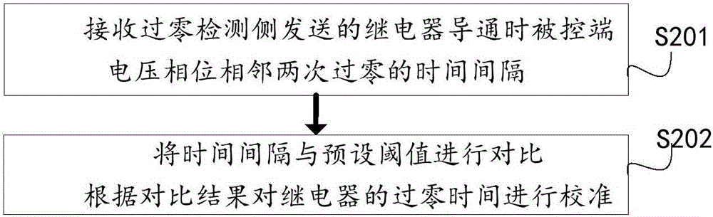
[0057] The embodiment of the present invention also provides a relay zero-crossing calibration method for the zero-crossing calibration side, see figure 2 , including the following steps:

[0058] Step 201 , receiving the time interval between two adjacent zero-crossing phases of the voltage phase of the controlled terminal when the relay is turned on from the zero-crossing detection side.

[0059] In this step, wireless communication protocols such as bluetooth, wifi, and zigbee can be used on the zero-crossing calibration side. The zigbee wireless communication protocol is preferably used to reduce product costs and ensure reliable data transmission. Smart electronic products through the zigbee communication protocol make the product not limited by the number of live wires, neutral wires, and channels, and the remote control of the product can be realized through smart devices, which is convenient for realizing home intelligence.

[0060] Step 202, comparing the time inte...

Embodiment 3

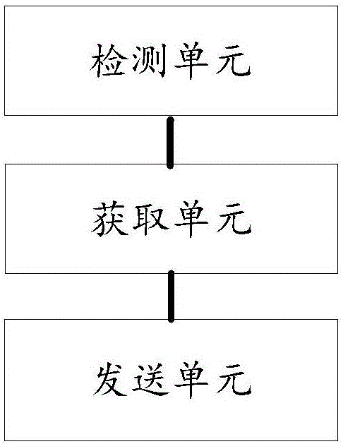
[0069] see image 3 , the embodiment of the present invention also provides a relay zero-crossing detection device, including:

[0070] The detection unit is used to detect the voltage phase of the controlled terminal of the relay when the relay is turned on;

[0071] An acquisition unit, configured to acquire the time interval between two adjacent zero-crossings of the voltage phase;

[0072] Sending unit for sending the time interval to the zero-crossing calibration side of the relay.

[0073] Further, the sending unit uses the zigbee wireless communication protocol to send the time interval to the zero-crossing calibration side of the relay. In the embodiment of the present invention, the zigbee wireless communication protocol is preferably adopted. The Zigbee protocol has short propagation distance, low power consumption, low cost, and simple protocol, which can effectively reduce the cost of the zero-crossing detection side and ensure reliable data transmission.

[00...


PUM


Abstract

The invention discloses a relay zero-cross detection method and device and a relay zero-cross calibration method and device. The relay zero-cross detection method comprises the following steps: when a relay is turned on, monitoring the voltage phase of a controlled end of the relay; obtaining the time interval of adjacent two times of zero-cross of the voltage phase; and sending the time interval to the zero-cross calibration side of the relay. The relay is detected by setting the independent zero-cross detection device, and is free of requirement for product circuit; and meanwhile, the relay does not need to be screened again, so that the research and development time of the product can be effectively reduced, and the production cost of the product is reduced.

Description

technical field [0001] The invention relates to the technical field of relay control, in particular to a relay zero-crossing detection and calibration method and device. Background technique [0002] With the development of the smart home industry, home smart products are becoming more and more diverse. Controlling lights and curtains through mobile phones has appeared in ordinary people's homes. Ordinary mechanical switches for controlling lights can no longer meet the requirements, so smart switches have emerged. Intelligent switch control loads generally use relays as switches to control their on-off. Ordinary resistive or inductive loads such as light bulbs, energy-saving lamps, and curtain motors are no problem. But now that LED energy-saving lamps appear, because they are capacitive loads, when the load is turned on, the surge current has a very large impact on the relay contacts. After switching several times, the relay contacts will be damaged, causing the relay to...

Claims


Application Information

Patent Timeline
Patent Type & Authority Applications(China)
IPC IPC(8): H02H3/08
CPCH02H3/08
Inventor 王建明
Owner QINGDAO HAIER INTELLIGENT HOME TECH CO LTD
Why Eureka
Try Eureka