Intelligent charging method for convenient rotary-type movable charging pile
An intelligent charging method and technology of mobile charging piles, which are applied in electric vehicle charging technology, secondary battery charging/discharging, charging stations, etc., can solve the problems of inconvenient monitoring, no protection structure, and easy theft of electric vehicles, and achieve The effect of avoiding theft, structural stability, and overall structural stability
- Summary
- Abstract
- Description
- Claims
- Application Information
AI Technical Summary
Problems solved by technology
Method used
Image

Examples
Embodiment 1
[0024] An intelligent charging method for a convenient rotating movable charging pile, comprising the following steps:
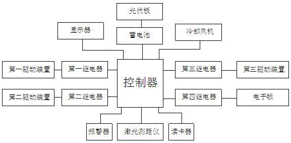
[0025] S1: When charging is required, swipe the card through the card reader. When the card information is successfully matched, the controller sends a driving signal to the fourth relay to open the electronic lock, and the controller sends a driving signal to the first relay. Start the first driving device, the first driving device pushes the rack to drive the gear to rotate, the gear drives the rotating shaft to rotate, and the rotating shaft drives the charging station to rotate;
[0026] S2: When the charging station rotates 180 degrees, the controller sends a driving signal to the second relay to start the second driving device, and the end of the second driving device is clipped into the positioning hole on the charging station;
[0027] S3: Start the conversion circuit, store the electric energy converted by the photovoltaic panel in the battery, and ...
PUM
 Abstract
Description
Claims
Application Information
PatSnap Eureka turns technology decisions into work you can execute. Powered by our Innovation Knowledge Graph, it runs expert workflows across engineering, life sciences, materials and intellectual property. Get your review-ready output in minutes.


