Glue injection equipment

An equipment and glue injection technology, applied in the direction of coating, device for coating liquid on the surface, etc., can solve problems such as needle deformation, product contamination, replacement, etc., to prevent collision deformation or bending, increase production, and quickly align Effect

Inactive Publication Date: 2016-09-28
FINETOP SCI &TECH
View PDF12 Cites 3 Cited by
  • Summary
  • Abstract
  • Description
  • Claims
  • Application Information

AI Technical Summary

Problems solved by technology

[0005] In actual use, it is found that there are some shortcomings in this glue injection equipment: 1. The position of the needle and the product to be glued must be kept in a relatively fixed position, and deviations are not allowed, otherwise the glue will be injected in unnecessary places. position, leading to product contamination and scrapping, or the occurrence of pin strikes, resulting in deformation and bending of the needle, which must be replaced with a new needle, which seriously affects production efficiency; Very high consistency, if the positioning parts of the tooling are inconsistent due to wear, it will lead to the contamination of the striker and the product, which will cause serious quality problems for large-scale products

Method used


Image

  • Glue injection equipment
  • Glue injection equipment
  • Glue injection equipment

Examples


Embodiment 1

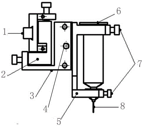
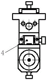
[0025] Such as Figure 4 As shown, a glue injection equipment includes an equipment fixing frame 1, a front and rear adjustment frame 2, an up and down adjustment frame 3, a left and right adjustment frame 4, a syringe fixing frame 7, and a syringe 8. The up and down adjustment frame 3 is installed on the equipment to be fixed Frame 1, the front and rear adjustment frame 2 is installed on the upper and lower adjustment frame 3, the left and right adjustment frame 4 is installed on the front and rear adjustment frame 2, the syringe fixing frame 7 is installed on the left and right adjustment frame 4, the needle cylinder 8 is equipped with a needle 10 and is installed on a syringe holder 7 which is slidably mounted on the guide rails 6 on the side of the left and right adjusting frame 4 through the sliding block 5 on the side. The syringe 8 is installed on the syringe fixing frame 7 and fixed with the syringe fixing screw 9.

Embodiment 2

[0027] Such as Figure 4 As shown, a glue injection equipment includes an equipment fixing frame 1, a front and rear adjustment frame 2, an up and down adjustment frame 3, a left and right adjustment frame 4, a syringe fixing frame 7, and a syringe 8. The up and down adjustment frame 3 is installed on the equipment to be fixed Frame 1, the front and rear adjustment frame 2 is installed on the upper and lower adjustment frame 3, the left and right adjustment frame 4 is installed on the front and rear adjustment frame 2, the syringe fixing frame 7 is installed on the left and right adjustment frame 4, the needle cylinder 8 is equipped with a needle 10 and is installed on a syringe holder 7 which is slidably mounted on the guide rails 6 on the side of the left and right adjusting frame 4 through the sliding block 5 on the side. The syringe 8 is installed on the syringe fixing frame 7 and fixed with the syringe fixing screw 9.

[0028] The front and rear adjustment frame 2, the up an...


PUM


Abstract

The invention discloses glue injection equipment. The glue injection equipment comprises an equipment fixed frame, front-and-back adjusting frames, up-and-down adjusting frames, left-and-right adjusting frames, needle cylinder fixing frames and needle cylinders; the up-and-down adjusting frames are installed on the equipment fixed frame, each front-and-back adjusting frame is installed on the corresponding up-and-down adjusting frame, each left-and-right adjusting frame is installed on the front-and-back adjusting frame, each needle cylinder fixing frame is installed on the corresponding left-and-right adjusting frame, each needle cylinder is provided with a needle and installed on the corresponding needle cylinder fixing frame, and each needle cylinder fixing frame is installed on a guide rail on the side portion of the corresponding left-and-right adjusting frame in an up-and-down sliding mode through a sliding block on the side portion. According to the glue injection equipment, the needles can be rapidly aligned to products to be subjected to glue injection, and a lot of time consumed due to a small deviation for adjustment is not needed; the needles can make contact with an upper deviation and keep still in the glue injection process, by means of the sliding blocks and the guide rails, the needle cylinder fixing frames can move upwards along the guide rails automatically, collision deformation or bending of the needles is prevented, and therefore protection on the needles is achieved, and new needles do not need to be replaced frequently.

Description

Technical field [0001] The invention relates to a glue injection equipment, which belongs to the field of optical communication device manufacturing, and can be used to inject glue to some products that need glue. Background technique [0002] During the assembly process of the optical transceiver, which is the core component of the optical transceiver module, some bonding processes are involved, and it is necessary to use equipment tooling to inject glue into the bonding position in advance. [0003] The glue injection equipment currently used by the applicant such as figure 1 , 2 , 3 shown. The glue injection equipment includes an equipment fixing frame 1, an up and down adjustment frame 2, a front and rear adjustment frame 3, a left and right adjustment frame 4, a needle cylinder fixing frame 5 and a needle cylinder 6. The equipment fixing frame 1 is used for connecting with fixed equipment, and plays a role of fixing the entire glue injection equipment. The up and down adjust...

Claims


Application Information

Patent Timeline
IPC IPC(8): B05C5/02B05C11/00
CPCB05C5/027B05C11/00
Inventor 陈于陈先华
Owner FINETOP SCI &TECH
Why Eureka
Try Eureka