
Pressure casting injector

A technology of injection device and plunger head, applied in the field of injection device for die casting, can solve problems such as casting wrinkles, and achieve the effect of suppressing casting wrinkles

Active Publication Date: 2016-09-28
TOYOTA JIDOSHA KK
View PDF6 Cites 4 Cited by
  • Summary
  • Abstract
  • Description
  • Claims
  • Application Information

AI Technical Summary

Problems solved by technology

[0006] Therefore, there is a problem of so-called casting wrinkles at the interface between the molten metal injected from the inner tip and the molten metal injected from the outer tip.

Method used


Image

  • Pressure casting injector
  • Pressure casting injector
  • Pressure casting injector

Examples


no. 1 approach

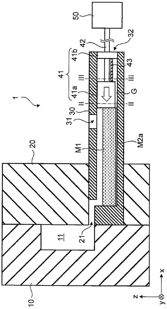
[0029] First, refer to figure 1 , a die casting apparatus using the injection apparatus according to the first embodiment of the present invention will be described. figure 1 It is a schematic cross-sectional view of a die casting apparatus using the injection apparatus according to the first embodiment of the present invention. like figure 1 As shown, the die casting apparatus includes a movable mold 10 , a fixed mold 20 , and an injection device 1 . Here, the injection device 1 according to the first embodiment of the present invention is an injection device for die casting, and includes a plunger sleeve 30 , a plunger head 41 , a plunger rod 42 , a protection plate 43 , and a drive source 50 .

[0030] Also, of course, figure 1 The right-handed xyz coordinates shown are used to facilitate the description of the positional relationship of the constituent elements. figure 1 The xy plane in the y plane constitutes the horizontal plane, and the z-axis direction is the verti...


PUM


Abstract

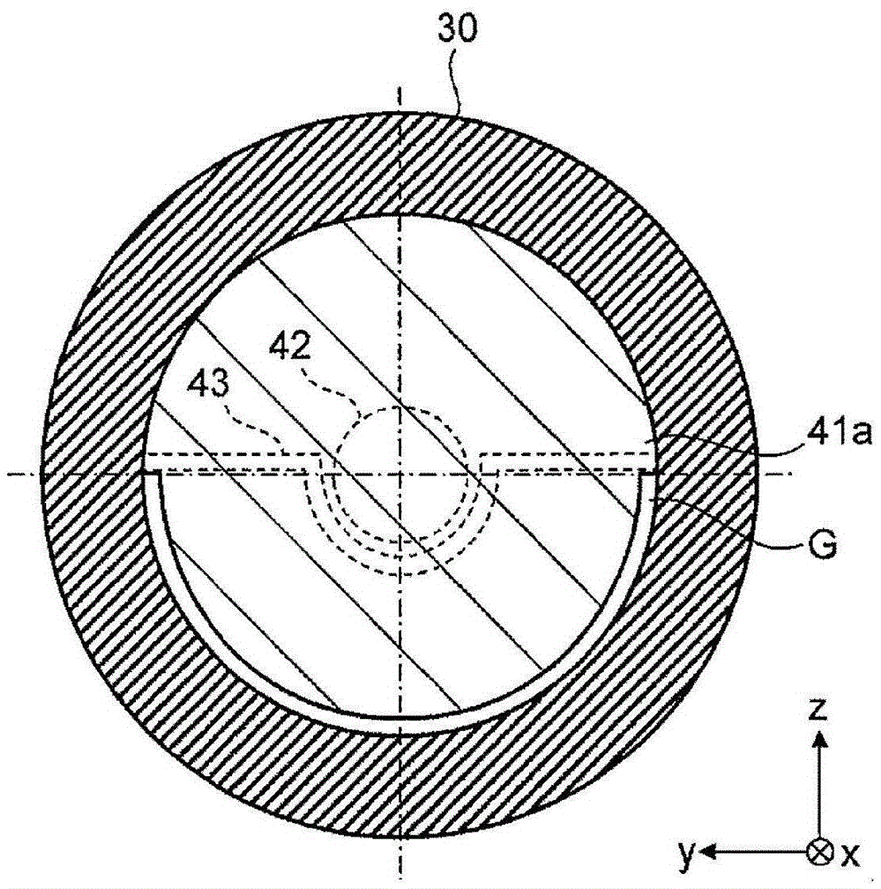
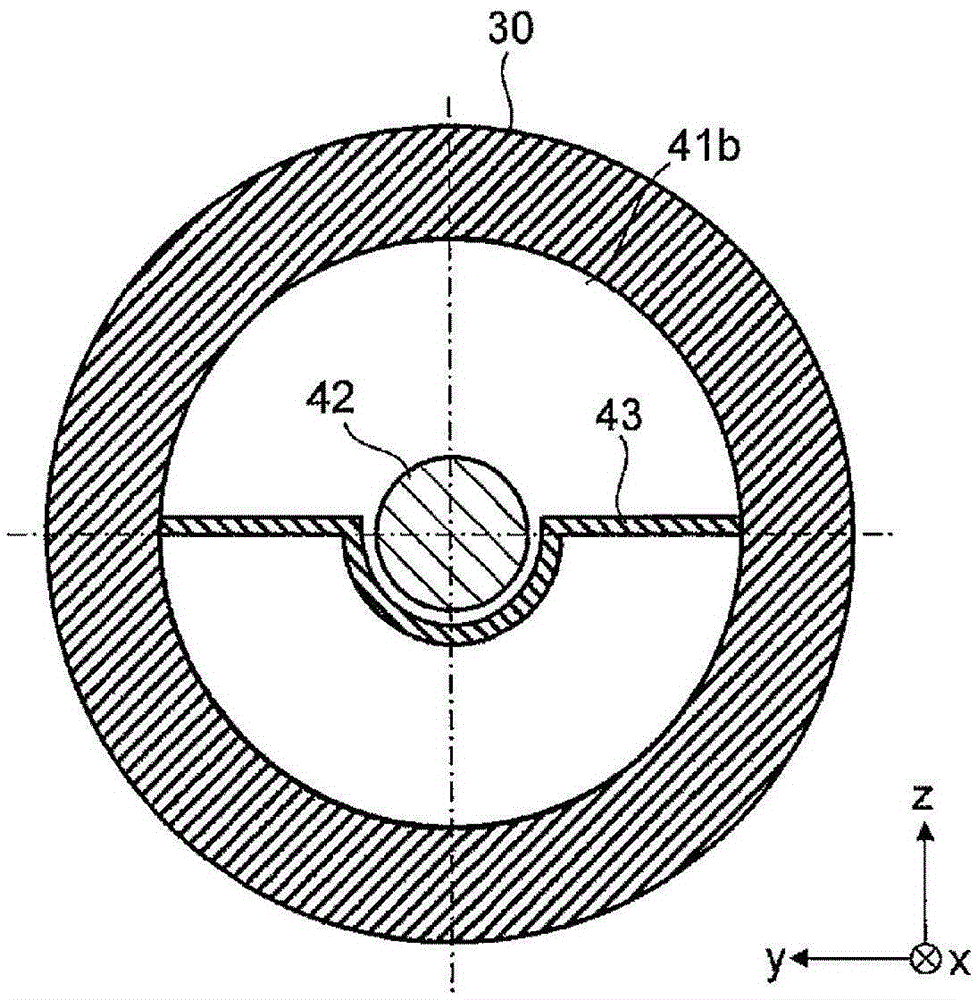
The invention provides a pressure casting injector, wherein the injector can prevent initial solidification sheet from mixing into casting, and can prevent casting lap from being generated; the pressure casting injector (1) comprises the following members: a sleeve (30) supplied to molten metal (M1); a first plug (41a) with a gap between inner surface of the sleeve (30) making contacts with the molten metal (M)1; a second plug (41b) sliding with the first plug (41a) and arranged in a rear direction closer to the extrusion direction of the molten metal (M1) when compared with the first plug. The sleeve (30) comprises a discharge port (32) used for discharging solidification sheets (M2a), captured between eh first and second plugs (41a, 41b), to the outer side; the second plug (41b) slides to the discharge port (32), thus discharging the solidification sheet (M2a) outside the sleeve (30) through the discharge port (32a).

Description

technical field [0001] The present invention relates to an injection device for die casting. Background technique [0002] In the injection device for die casting, after the molten metal is supplied to the cylindrical plunger sleeve, the plunger head advances in the plunger sleeve, thereby injecting the molten metal into the cavity of the metal mold. When molten metal is supplied to the plunger sleeve, the molten metal in contact with the plunger sleeve is cooled and solidified. Thus, initially solidified flakes are formed on the inner surface of the plunger sleeve that contacts the molten metal. When the plunger head is advanced in the plunger sleeve, if the initially solidified piece is peeled from the plunger sleeve and injected into the cavity of the metal mold together with the molten metal, it will become a casting defect. [0003] Japanese Patent Laid-Open No. 2000-263209 discloses a plunger head having a dual structure composed of an inner front end and an outer fr...

Claims


Application Information

Patent Timeline
Patent Type & Authority Applications(China)
IPC IPC(8): B22D17/20
CPCB22D17/2015
Inventor 安孙子由太
Owner TOYOTA JIDOSHA KK
Learn More