New tension mandrel

A new type of mandrel technology, applied in the direction of expanding the mandrel, can solve the problems of increasing the difficulty of machining parts, small allowances, and troublesome manufacturing, so as to meet the needs of finishing, eliminate deformation errors, and reduce production costs.

Active Publication Date: 2017-12-29
佛山市顺德区柏嘉盛五金制品有限公司
View PDF5 Cites 0 Cited by
  • Summary
  • Abstract
  • Description
  • Claims
  • Application Information

AI Technical Summary

Problems solved by technology

Due to the low strength of the claw body material itself, the soft three-claw is easy to deform the clamping part under the action of a large clamping force, so it is only suitable for rough machining; if you want to achieve high-precision machining, you can only use friction mandrel b or expandable mandrel c
Among them, the tapered friction mandrel b (such as figure 2 As shown), although the structure is simple and easy to manufacture, the friction mandrel b is only suitable for finishing with a small allowance, and the accuracy of the positioning hole of the workpiece is high, which increases the processing difficulty of the part, and at the same time, the friction mandrel b is easy to wear , so it is not suitable for batch processing
Expandable mandrel c (such as image 3 As shown) the structure is relatively complex, most of them are special fixtures, the production cycle is long, labor-intensive and time-consuming
However, for other cover parts d that are positioned by holes and process inner and outer cylindrical surfaces and end faces with holes (such as Figure 4 Shown), generally also use expandable mandrel e (such as Figure 5 shown) for processing, this type of expandable mandrel e structure is simpler than the above expandable mandrel c, but these two kinds of expandable mandrels c and e are more troublesome to manufacture, especially for production tasks When the schedule requirements are very urgent, it will take a long time to make the tooling, which cannot meet the needs of the production schedule. There is an urgent need for a fast and simple processing tooling to relieve the pressure on production. The following technical solutions are proposed

Method used


Image

  • New tension mandrel
  • New tension mandrel
  • New tension mandrel

Examples


Embodiment Construction

[0024] Attached below Figure 6-8 An embodiment of the present invention is described.

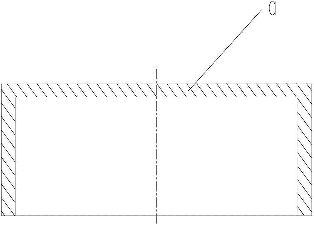
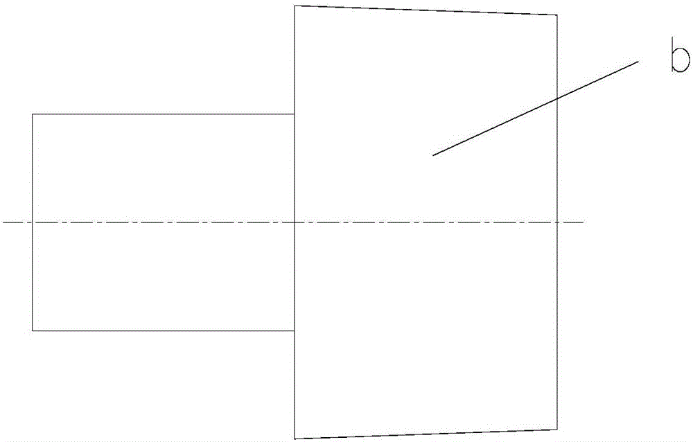
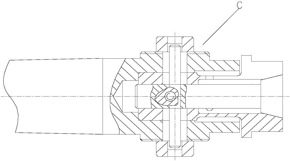
[0025] The new tension mandrel has an integrated mandrel clamp body 1. The integrated mandrel clamp body 1 lays the foundation for the coaxiality of the fixture, structural rigidity, and reduced manufacturing difficulty. The mandrel One end of the clamp body 1 is the clamping part 11 and the other end is the positioning part 12, and the tension part 13 is between the clamping part 11 and the positioning part 12; Groove 14, and the groove widths I and II of the tensioning groove 14 are symmetrical to the center line of the mandrel. Through this symmetry, the coaxiality of the fixture during the tensioning process can be ensured, the tensioning error can be reduced, and the machining accuracy can be guaranteed. Among them, The groove width I at the positioning part 12 is 0.5-5mm, and the groove width II at the tensioning part 13 is 1 / 5-1 / 3 of the diameter of the tensioning part 13. During ...


PUM


Abstract

A new type of expansion mandrel is provided, which has a mandrel clamp body, the mandrel clamp body is integrally made, one end of which is a clamping part and the other end is a positioning part, and the tension part is between the clamping part and the positioning part , the positioning part and the tensioning part are made with tensioning slots along the axial direction of the mandrel, and the groove widths of the tensioning slots I and II are symmetrical along the center line of the mandrel; the tensioning part is made with a radial direction of the mandrel Threaded hole, the threaded hole is screwed with a suitable screw and the end surface of the screw is pressed against the groove surface of the tension slot to clamp the part with tension; the axial positioning surface of the positioning part is slidably matched with the positioning surface of the part and Full contact. The present invention uses shaft grooves and radially drills threaded holes without making special tapered screws, and uses standard screws for tension clamping. The fixture has the advantages of good overall structure rigidity, simple manufacture, wide applicability and low cost.

Description

technical field [0001] The invention belongs to the technical field of machining fixtures, and in particular relates to a novel tension mandrel which processes an outer circle and an end surface by positioning an inner hole. Background technique [0002] For cover parts a (such as figure 1 As shown), it cannot be compressed axially during processing, but can only be clamped radially. The fixture generally adopts three types of soft three-jaw, friction mandrel or expandable mandrel. Due to the low strength of the claw body material itself, the soft three-claw is easy to deform the clamping part under the action of a large clamping force, so it is only suitable for rough machining; if you want to achieve high-precision machining, you can only use friction mandrel b or expandable mandrel c. Among them, the tapered friction mandrel b (such as figure 2 As shown), although the structure is simple and easy to manufacture, the friction mandrel b is only suitable for finishing wi...

Claims


Application Information

Patent Timeline
Patent Type & Authority Patents(China)
IPC IPC(8): B23B31/40
CPCB23B31/4073
Inventor 吕芸芬雒文军
Owner 佛山市顺德区柏嘉盛五金制品有限公司
Why Eureka
Try Eureka