Thin-wall pipe cutting device

A technology for cutting equipment and thin-walled pipes, applied in the field of thin-walled pipe cutting equipment, can solve the problems of reduced production efficiency, tearing of thin-walled pipe walls, waste of raw materials, etc., and achieve the effect of uniform internal and external forces and smooth cutting edges

Active Publication Date: 2016-09-28
山东奥维特汽车零部件有限公司
View PDF6 Cites 6 Cited by
  • Summary
  • Abstract
  • Description
  • Claims
  • Application Information

AI Technical Summary

Problems solved by technology

In this cutting process, because the extrusion force of the cutting blade on the thin-walled tube is concentrated at one point, and the tube wall of the thin-walled tube is relatively thin, the wall of the thin-walled tube often tears during the cutting process, resulting in uneven cutting It is flat, and the cutting edge needs to be trimmed before it can be used, which not only causes waste of raw materials, but also reduces production efficiency

Method used


Image

  • Thin-wall pipe cutting device
  • Thin-wall pipe cutting device

Examples


Embodiment Construction

[0018] The specific embodiments of the present invention will be further described below in conjunction with the accompanying drawings. It should be noted here that the descriptions of these embodiments are used to help understand the present invention, but are not intended to limit the present invention. In addition, the technical features involved in the various embodiments of the present invention described below may be combined with each other as long as they do not constitute a conflict with each other.

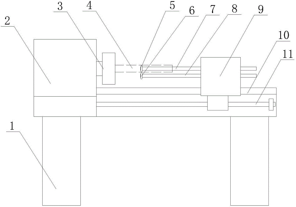
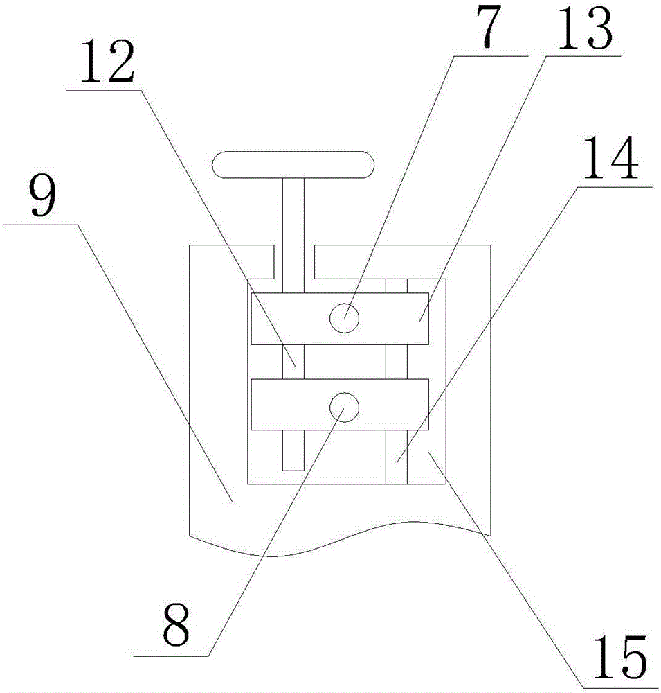
[0019] combined with figure 1 , 2 The present invention is further described to enable those skilled in the art to better implement the present invention. A thin-walled pipe cutting device of the present invention includes a rotating fixing mechanism, a cutting mechanism and a bed 1 for fixing the rotating mechanism and the cutting mechanism.

[0020] The upper end of the bed 1 of the present invention is provided with a guide rail 10 , one end of the guide rail 10 is ...


PUM


Abstract

The invention discloses a thin-wall pipe cutting device. The thin-wall pipe cutting device comprises a rotating fixing machine and a cutting machine, wherein the cutting machine comprises a first gyring blade and a second gyring blade; the first gyring blade extends into a thin-wall pipe, and the second gyring blade is arranged at the outer side of the thin-wall pipe; the first gyring blade and the second gyring blade are matched to cut the thin-wall pipe. According to the thin-wall pipe cutting device, the two gyring blades are provided; one gyring blade extends into the thin-wall pipe, and another gyring blade is arranged at the outer side of the thin-wall pipe; the two blades are adjusted to be tangential to each other during the cutting process and can synchronously extrude the thin-wall pipe from the inside and the outside so as to enable uniform internal and external stressing, and as a result, a port formed by cutting is flat, and the circumstance that the thin-wall pipe is broken can be avoided.

Description

technical field [0001] The invention relates to the technical field of mechanical processing equipment, in particular to thin-walled pipe cutting equipment. Background technique [0002] During the cutting process of the thin-walled tube (with a wall thickness of 0.3-0.6mm), the cutting blade is set on the outside of the thin-walled tube. During the cutting process, the thin-walled tube rotates, and the cutting blade squeezes the thin-walled tube. Press to complete the cutting work of thin-walled tubes. In this cutting process, because the extrusion force of the cutting blade on the thin-walled tube is concentrated at one point, and the tube wall of the thin-walled tube is relatively thin, the wall of the thin-walled tube often tears during the cutting process, resulting in uneven cutting It is flat, and the cutting edge needs to be trimmed before it can be used, which not only causes waste of raw materials, but also reduces production efficiency. Contents of the inventio...

Claims


Application Information

Patent Timeline
Patent Type & Authority Applications(China)
IPC IPC(8): B23D21/00
CPCB23D21/00
Inventor 侯海波刘磊张德清
Owner 山东奥维特汽车零部件有限公司
Why Eureka
Try Eureka