Eccentric wheel, swing rod and sliding groove type coupling self-adaptation robot finger device
What is Al technical title?
Al technical title is built by PatSnap Al team. It summarizes the technical point description of the patent document.
A robot finger and eccentric wheel technology, applied in the direction of manipulators, chucks, manufacturing tools, etc., can solve the problems of reduced grasping efficiency, weakened adaptability, small grasping range, etc., and achieve compact structure, large grasping range, small size effect
Inactive Publication Date: 2016-09-28
TSINGHUA UNIV
View PDF7 Cites 3 Cited by
Summary
Abstract
Description
Claims
Application Information
AI Technical Summary
This helps you quickly interpret patents by identifying the three key elements:
Problems solved by technology
Method used
Benefits of technology
Problems solved by technology
[0006] However, the traditional underactuated robot hand mostly uses a link mechanism. Due to the limitation of the mechanism, the finger segment has an extreme position in the process of leaning against the object, resulting in a motion dead zone, and the adaptability is greatly weakened.
[0007] An existing double-joint co-direction transmission composite underactuated robot finger device, such as Chinese patent CN102161204B, can realize the function of coupling and rotating multiple joints first, and then adaptively grasping. Dead zone, the grasping range is small; when grasping the object, the object must be close to the base and the proximal finger segment at first, which reduces the grasping efficiency; the multi-way gear transmission is adopted, and the structure is complicated
Method used
Image
Click on the blue label to locate the original text in one second.
Reading with bidirectional positioning of images and text.
Examples
Embodiment Construction
[0039] The specific structure and working principle of the present invention will be further described in detail below in conjunction with the accompanying drawings and embodiments.
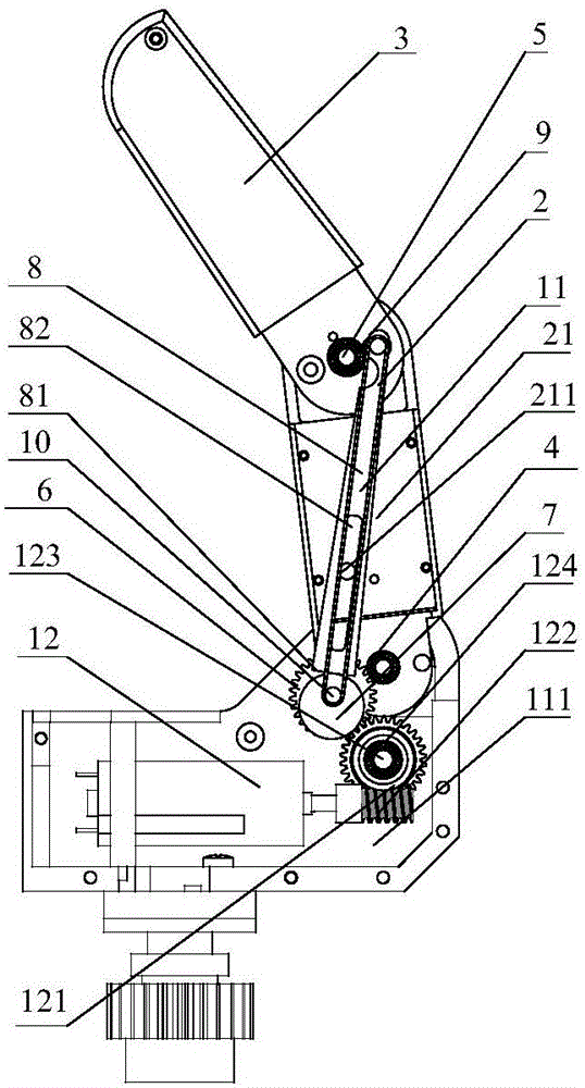
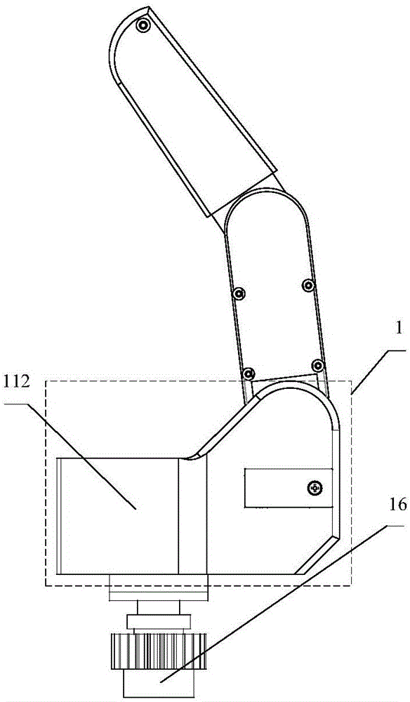
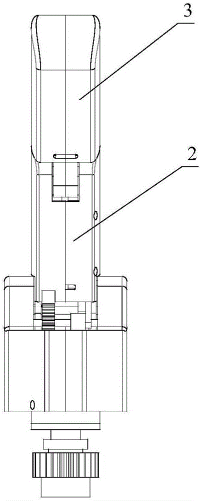
[0040] An embodiment of the eccentric wheel pendulum chute type coupling adaptive robot finger device 13 designed by the present invention, as Figure 1 to Figure 4 As shown, it includes a base body 1, a first finger segment 2, a second finger segment 3, a proximal joint shaft 4, a distal joint shaft 5 and a base driver 12; the proximal joint shaft 4 is sleeved in the base body 1 The first finger segment 2 is sleeved on the proximal joint shaft 4; the distal joint shaft 5 is sleeved in the first finger segment 2; the second finger segment 3 is sleeved on the distal joint shaft 5 ; The centerline of the proximal joint axis 4 is parallel to the centerline of the distal joint axis 5 .
[0041] This embodiment also includes a transmission mechanism, a slider 211, a base driving gear 6, an eccentric ...
PUM
Abstract
The invention discloses an eccentric wheel, swing rod and sliding groove type coupling self-adaptation robot finger device, and belongs to the technical field of robot hands. The eccentric wheel, swing rod and sliding groove type coupling self-adaptation robot finger device comprises a base body, two finger sections, a driver, a transmission mechanism, a sliding block, an eccentric wheel, a long swing rod, a swing rod shaft, a drive shaft, a spring piece and the like. The drive shaft is fixedly sleeved with the eccentric wheel. The second finger section is sleeved with one end of the long swing rod through the swing rod shaft, and the other end of the long swing rod is a round face. The round face of the swing rod is in sliding contact with the eccentric wheel. The long swing rod is provided with a sliding groove. The sliding block is fixedly connected with the first finger section. The sliding block slides in the sliding groove. The spring is connected with the drive shaft and the swing rod shaft. The eccentric wheel, swing rod and sliding groove type coupling self-adaptation robot finger device comprehensively achieves the coupling self-adaptation enveloping and grabbing function. Two knuckles are driven by one motor of the device, when the device does not make contact with an object, the rotating speed of the second finger section is higher than that of the first finger section, and a coupling effect is achieved. After the first finger section makes contact with the object, the second finger section continues to rotate, and a self-adaptation function is achieved. The device is wide in grabbing range, compact in structure, small in size, free of complex sensing and control systems, low in manufacturing and maintaining cost, and suitable for the robot hands.
Description
technical field [0001] The invention belongs to the technical field of robot hands, and in particular relates to the structural design of an eccentric wheel swing rod chute-type coupling self-adaptive robot finger device. Background technique [0002] The adaptive underactuated robot hand uses a small number of motors to drive joints with multiple degrees of freedom. Due to the small number of motors, the motors hidden in the palm can choose larger power and volume, and the output is large. At the same time, the purely mechanical feedback system does not need to be sensitive to the environment. It can achieve stable grasping, automatically adapt to objects of different shapes and sizes, does not require real-time electronic sensing and closed-loop feedback control, and is simple and convenient to control, reducing manufacturing costs. [0003] In the process of traditional underactuated robot fingers approaching the object, the far finger segment is relatively stationary rel...
Claims
Application Information
Patent Timeline
Application Date:The date an application was filed.
Publication Date:The date a patent or application was officially published.
First Publication Date:The earliest publication date of a patent with the same application number.
Issue Date:Publication date of the patent grant document.
PCT Entry Date:The Entry date of PCT National Phase.
Estimated Expiry Date:The statutory expiry date of a patent right according to the Patent Law, and it is the longest term of protection that the patent right can achieve without the termination of the patent right due to other reasons(Term extension factor has been taken into account ).
Invalid Date:Actual expiry date is based on effective date or publication date of legal transaction data of invalid patent.
