
Magnetically-driven leftover extruder

A technology of magnetic drive and extruder, applied in the direction of stamping machines, presses, manufacturing tools, etc., can solve the problems of time-consuming and labor-intensive cleaning, difficult transportation efficiency, and reduced production efficiency, so as to save transportation space, save storage space, and improve The effect of transport efficiency

Inactive Publication Date: 2016-09-28
覃天钊
View PDF10 Cites 0 Cited by
  • Summary
  • Abstract
  • Description
  • Claims
  • Application Information

AI Technical Summary

Problems solved by technology

[0002] In the leather processing industry, the production and processing of sheepskin, cowhide and other leather products need to be cut and scrapped, and some leftover leathers are inevitably produced. Enterprises need to deal with these leftovers, because most of the leather leftovers are small pieces or Filamentous and relatively fluffy, cleaning is time-consuming and laborious; if it is piled up, it will take up a lot of space, and if left untreated for a long time, it will rot and pollute the environment and surrounding groundwater. If it is burned, it will pollute the environment even more
Most of the companies transport the leftovers of leather for processing, but as the international oil price not only rises, but also the domestic refined oil remains high, the cost of motor vehicle transportation has not only increased, but how to improve the transportation efficiency has become a difficult problem
Moreover, after the waste is formed, the equipment sent out often has the problem of colliding with the ground and loosening, so it must be formed twice, which reduces the production efficiency

Method used


Image

  • Magnetically-driven leftover extruder

Examples


Embodiment Construction

[0019] The present invention will be described in detail below in conjunction with the accompanying drawings. The description in this part is only exemplary and explanatory, and should not have any limiting effect on the protection scope of the present invention.

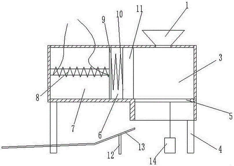
[0020] like figure 1 A magnetically driven leftover extruder shown includes a cylinder body 2, a feed port 1 and a bottom cover 5,

[0021] The cylinder body 2 has a rectangular cross section, and the cylinder body 2 includes a piston cavity 6, an electromagnetic cavity 7 on the left side of the piston cavity 6, and a molding cavity 3 on the right side of the piston cavity 6,

[0022] A square partition plate 9 is arranged at the joint between the electromagnetic cavity 7 and the piston cavity 6 to separate the electromagnetic cavity 7 from the piston cavity 6,

[0023] An electromagnetic structure 8 is installed in the electromagnetic cavity 7, and a magnetic pole of the electromagnetic structure 8 is arranged at ...


PUM


Abstract

The invention discloses a magnetically-driven leftover extruder. The cross section of a barrel body is rectangular; a joint of an electromagnetic cavity and a piston cavity is provided with a square separating plate for separating the electromagnetic cavity from the piston cavity; an electromagnetic structure is mounted in the electromagnetic cavity; one magnetic pole of the electromagnetic structure is arranged on the center position of the separating plate; a piston which is sliding fit to the inner wall of the piston cavity and the inner wall of a forming cavity is arranged in the piston cavity; an oil cylinder is mounted below a bottom cover; a transmission rod of the oil cylinder is hinged with the bottom cover; a slide path which is arranged in an inclined manner is arranged below the electromagnetic cavity; and the upper part of the electromagnetic cavity is supported by a supporting rod. According to the magnetically-driven leftover extruder, quick compaction and formation of a great large number of leftovers can be realized, stacking space of the leftovers is effectively saved, storage site of a plant is saved, transportation space is saved, transportation efficiency is improved, quick treatment on leftovers is realized; and moreover, the problem that the leftovers must be re-molded due to the fact that the molded leftovers are loosened as a result of collision with ground is solved, so that working efficiency is improved.

Description

technical field [0001] The invention relates to the technical field of leather processing equipment, in particular to a magnetically driven scrap extrusion machine. Background technique [0002] In the leather processing industry, the production and processing of sheepskin, cowhide and other leather products need to be cut and scrapped, and some leftover leathers are inevitably produced. Enterprises need to deal with these leftovers, because most of the leather leftovers are small pieces or Filamentous and relatively fluffy, it is time-consuming and laborious to clean up; if it is piled up, it will take up a lot of space, and it will rot if left untreated for a long time, polluting the environment and surrounding groundwater, and it will pollute the environment even more if it is burned. Most companies transport the leftovers of leather for processing. However, as the international oil price not only rises, but also the domestic refined oil remains high, the cost of motor ve...

Claims


Application Information

Patent Timeline
IPC IPC(8): B30B9/28B30B1/42
CPCB30B9/28B30B1/42
Inventor 覃天钊
Owner 覃天钊
Learn More