A cargo orientation adjustment device for a transport vehicle
A technology for azimuth adjustment and transportation vehicles, applied in the field of transportation vehicles, can solve the problems of high cost and complex structure, and achieve the effects of low cost, simple structure and improved rotating function.
- Summary
- Abstract
- Description
- Claims
- Application Information
AI Technical Summary
Problems solved by technology
Method used
Image
Examples
Embodiment 1
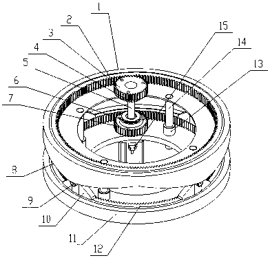
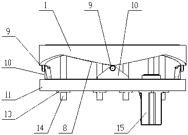
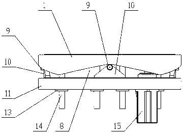
[0042] As shown in the figure, a cargo orientation adjustment device for a transport vehicle includes a guide mechanism, a drive rod 5, an upper clutch 4, a lower clutch 6, an upper drive wheel 3, a lower drive wheel 7, an upper turntable and a lower turntable; the upper clutch 4 and the lower clutch 6 are respectively connected with the upper driving wheel 3 and the lower driving wheel 7, and cooperate with the driving rod 5, and one end of the driving rod 5 is connected with the motor 15, and the motor 15 is a two-way motor; the upper turntable includes the inner ring of the upper turntable 2 and the upper turntable outer ring 1, there are balls between the upper turntable inner ring 2 and the upper turntable outer ring 1, the lower turntable includes the lower turntable inner ring 12 and the lower turntable outer ring 11, the lower turntable inner ring 12 and the lower turntable outer ring Balls are arranged between 11, and the inner ring 2 of the upper turntable and the inn...
Embodiment 2
[0047]As shown in the figure, a cargo orientation adjustment device for a transport vehicle includes a guide mechanism, a drive rod 5, an upper clutch 4, a lower clutch 6, an upper drive wheel 3, a lower drive wheel 7, an upper turntable and a lower turntable; the upper clutch 4 and the lower clutch 6 are respectively connected with the upper drive wheel 3 and the lower drive wheel 7, and cooperate with the drive rod 5, and one end of the drive rod 5 is connected with the motor 15; the upper turntable includes the upper turntable inner ring 2 and the upper turntable outer ring 1. There is a "convex" gap between the inner ring 2 of the upper turntable and the outer ring 1 of the upper turntable. The lower turntable includes the inner ring 12 of the lower turntable and the outer ring 11 of the lower turntable. There is a "convex" shaped gap between them, the inner ring 2 of the upper turntable and the inner ring 12 of the lower turntable are respectively connected with the upper ...
Embodiment 3
[0052] Embodiment 3 is basically the same as Embodiment 2, the difference is that there is a stepped gap between the inner ring 2 of the upper turntable and the outer ring 1 of the upper turntable, and there is a gap between the inner ring 12 of the lower turntable and the outer ring 11 of the lower turntable. Step-shaped gap, there are four curved surface groups on the outer ring 1 of the upper turntable, the number of curved surfaces in each group of curved surfaces is two, and the height of the curved surfaces is the same; the slopes of the curved surfaces in the curved surface groups are different, and the highest point of the curved surface is Available with grooves or smooth transitions.
PUM
 Abstract
Description
Claims
Application Information
 - R&D
- Intellectual Property
- Life Sciences
- Materials
- Tech Scout
- Unparalleled Data Quality
- Higher Quality Content
- 60% Fewer Hallucinations
Browse by: Latest US Patents, China's latest patents, Technical Efficacy Thesaurus, Application Domain, Technology Topic, Popular Technical Reports.
© 2025 PatSnap. All rights reserved.Legal|Privacy policy|Modern Slavery Act Transparency Statement|Sitemap|About US| Contact US: help@patsnap.com


