Automatic defoaming device for fermentation tank

A technology of defoaming device and fermenter, applied in bioreactor/fermenter combination, specific-purpose bioreactor/fermenter, biochemical cleaning device, etc., can solve the problem of reducing the growth and reproduction speed of bacteria, affecting bacteria and Oxygen contact area, increased bacterial infection, etc.

Inactive Publication Date: 2017-06-30
嘉泽成华(天津)科技有限公司
View PDF0 Cites 1 Cited by
  • Summary
  • Abstract
  • Description
  • Claims
  • Application Information

AI Technical Summary

Problems solved by technology

As the cultivation time increases, the foam in the fermenter will continue to increase, and the increase in foam will affect the contact area between bacteria and oxygen, reducing the growth and reproduction speed of bacteria
If it is not treated, the foam will overflow the tank along the vent hole, which greatly increases the chance of bacterial infection, which may lead to product fermentation failure
[0003] Usually, the following two methods are adopted for the elimination of foam: one method is to close the inlet and outlet valves, stop stirring and wait for the foam to disappear, then reopen the valve and stir again, if the foam rises again, repeat the last action In this way, although the purpose of defoaming can be achieved, the fermentation cycle will be delayed; another method is to add the sterilized defoaming agent to the fermenter through the pipeline flow, which can also reduce the concentration of foam, but the flow Adding too much will also inhibit the growth of bacteria

Method used


Image

  • Automatic defoaming device for fermentation tank
  • Automatic defoaming device for fermentation tank

Examples


Embodiment Construction

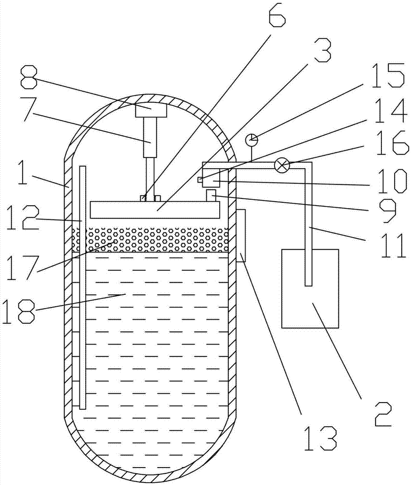
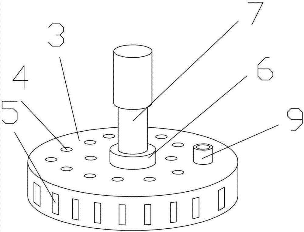
[0018] Combine below Figure 1-2 The present invention is further described:

[0019] An automatic defoaming device for a fermentation tank, which mainly includes a fermentation tank body 1, a foam collection device, a foam discharge device and a foam storage device 2. The foam collection device includes a foam collector 3, a telescopic rod 7 and a telescopic controller 8. The foam collector 3 is provided with an opening and closing hole 4 and a side opening and closing hole 5. The foam is collected by switching the opening and closing of the opening and closing hole 4 and the side opening and closing hole 5. The foam collector 3 is connected to the telescopic rod 7 through the threaded connection block 6, which is convenient Removed, the telescopic rod 7 is connected to the telescopic controller 8, and the telescopic controller 8 controls the telescopic rod 7 to extend and retract, so as to control the rise and fall of the foam collector 3, the telescopic controller 8 is arra...


PUM


Abstract

---- The invention discloses an automatic defoaming device for a fermentation tank, which mainly includes a fermentation tank body, a foam collecting device, a foam discharging device and a foam storage, the foam collecting device includes a foam collector, a telescopic rod and a telescopic controller, and the foam discharging device includes A foam outlet sleeve and a foam outlet tube, the foam outlet is connected to the foam outlet sleeve, the foam outlet sleeve is connected to a foam outlet tube, and the foam outlet tube is connected to the foam reservoir. The beneficial effects of the present invention are as follows: a foam collector is provided. When the foam collector is located in the foam layer, the opening and closing holes and the side opening and closing holes are opened, so that the foam enters the foam collector. After collecting for a period of time, the opening and closing holes and the side opening The closed cells are closed to achieve the purpose of automatic foam collection; there is a sensor to sense whether the foam discharge port enters the foam discharge port casing; the telescopic rod is controlled by the telescopic controller to achieve the purpose of lifting the foam collector.

Description

technical field [0001] The invention relates to a defoaming device, in particular to an automatic defoaming device for a fermentation tank, which belongs to the field of biological equipment. Background technique [0002] Before microbial fermentation, the culture medium and antifoaming agent are put into the fermentation tank and sterilized at high temperature. After sterilization, cooling, inoculation and cultivation are carried out. gradually weakened. As the incubation time increases, the foam in the fermenter will continue to increase, and the increase in foam will affect the contact area between bacteria and oxygen, reducing the growth and reproduction speed of bacteria. If not treated, the foam will overflow outside the tank along the vent hole, which greatly increases the chance of bacterial infection and may cause the product to fail to ferment. [0003] Usually, the following two methods are adopted for the elimination of foam: one method is to close the inlet an...

Claims


Application Information

Patent Timeline
Patent Type & Authority Applications(China)
IPC IPC(8): C12M1/21
CPCC12M41/02
Inventor 刘成荣
Owner 嘉泽成华(天津)科技有限公司
Why Eureka
Try Eureka