Stop mechanism

A blocking mechanism and blocking shaft technology, applied in the direction of conveyor objects, transportation and packaging, etc., can solve the problems of complex structure and high cost, and achieve the effect of easy operation and simple structure

Active Publication Date: 2016-09-28
BOZHON PRECISION IND TECH CO LTD
View PDF6 Cites 8 Cited by
  • Summary
  • Abstract
  • Description
  • Claims
  • Application Information

AI Technical Summary

Problems solved by technology

[0002] In the automatic assembly line assembly, when the carrier carries the product and flows through the working area, it needs to stop positioning in the working area before performing related operations. At this time, a mechanism that can stop the carrier and position the carrier is needed. The existing technology The blocking mechanism is a horizontal blocking device, which uses slide rail sliders and lifting cylinders to complete the blocking function, such as patent application: patent application number: 201511018414.8, which discloses the following technical features: including the bottom plate of the blocking cylinder, the blocking cylinder A blocking cylinder is installed on the bottom plate, and the upper end of the piston rod of the blocking cylinder is connected to the buffer fixing seat through the blocking cylinder joint; Outriggers integrally formed in a cylindrical structure; the left and right sides of the bottom plate of the blocking cylinder are respectively equipped with blocking s

Method used


Image

  • Stop mechanism
  • Stop mechanism
  • Stop mechanism

Examples


Embodiment Construction

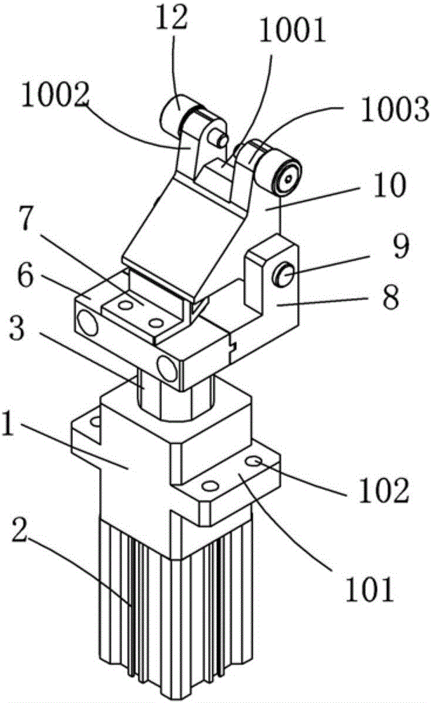
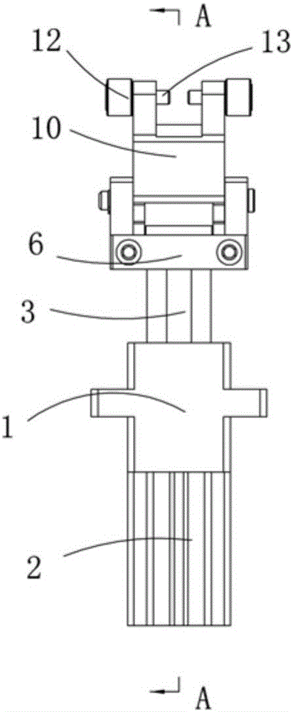
[0026] Examples, see attached Figure 1-7 , a blocking mechanism, including a lifting cylinder 2 installed at the bottom of a lifting cylinder fixing seat 1, the middle parts of the left and right sides of the lifting cylinder fixing seat are respectively provided with a flange 101 integrally formed with the lifting cylinder fixing seat, on the flange An installation hole 102 is provided, through which the lifting cylinder fixing base 1 can be fixed on other equipment or a fixing plate, so as to facilitate the fixing of the whole mechanism.

[0027] The upper end of the cylinder shaft of the lifting cylinder supports the blocking shaft 3, and the lower part of the blocking shaft extends into the fixing seat of the lifting cylinder, and the inside of the blocking shaft is provided with an elastic member 4 and an elastic top post 5, and the elastic part and the elastic top post Cooperate to form a buffer.

[0028] A longitudinal through hole 103 is provided in the fixed seat of...


PUM


Abstract

The invention relates to a stop mechanism. The stop mechanism comprises a lifting cylinder mounted at the bottom of a lifting cylinder fixing seat, wherein the upper end of a cylinder shaft of the lifting cylinder abuts against a stop shaft; the lower part of the stop shaft extends into the lifting cylinder fixing seat; an elastic piece and an elastic abutting column are arranged inside the stop shaft and are matched with each other to form a buffer; a stop shaft press plate is mounted at the upper end of the stop shaft; an elastic abutting column press plate is mounted on the stop shaft press plate; the upper part of the stop shaft is stopped by the elastic abutting column press plate; a bird hook base is arranged on the right side of the upper part of the stop shaft press plate; a bird hook is mounted on the bird hook base by the aid of a rotating shaft; the elastic abutting column abuts against the bird hook; the bird hook rotates around the rotating shaft and resets automatically by the aid of a torsional spring; and rollers which are inserted below a carrier and can stop the carrier are arranged on the bird hook. The stop mechanism is applied to assembly by the aid of an automatic assembly line, can stop and position the carrier, and is simple in structure, low in cost and easy to operate.

Description

Technical field: [0001] The invention relates to the field of blocking mechanism equipment, in particular to a blocking mechanism used for blocking buffering and positioning of a carrier. Background technique: [0002] In the automatic assembly line assembly, when the carrier carries the product and flows through the working area, it needs to stop positioning in the working area before performing related operations. At this time, a mechanism that can stop the carrier and position the carrier is needed. The existing technology The blocking mechanism is a horizontal blocking device, which uses slide rail sliders and lifting cylinders to complete the blocking function, such as patent application: patent application number: 201511018414.8, which discloses the following technical features: including the bottom plate of the blocking cylinder, the blocking cylinder A blocking cylinder is installed on the bottom plate, and the upper end of the piston rod of the blocking cylinder is ...

Claims


Application Information

Patent Timeline
IPC IPC(8): B65G47/88
CPCB65G47/8815
Inventor 吕绍林杨愉强王建福刘陈亮
Owner BOZHON PRECISION IND TECH CO LTD
Why Eureka
Try Eureka