
An automatic feeding color testing machine and its use method

An automatic feeding and color testing machine technology, applied in the field of color testing machines, can solve the problems of difficulty in simulating multiple additions, time-consuming and labor costs, and uncontrollable amount of release, saving manpower and time, reducing labor Errors, the effect of improving efficiency

Active Publication Date: 2019-02-26
广州市鸿通机械有限公司
View PDF6 Cites 0 Cited by
  • Summary
  • Abstract
  • Description
  • Claims
  • Application Information

AI Technical Summary

Problems solved by technology

This method has the following disadvantages: 1. It is necessary to weigh the required amount of auxiliary agent in advance, and then add it to the injection cup. It is necessary to manually open the piston, which is prone to human errors, time-consuming and labor costs; 2. Usually, each dyeing cup is only equipped with One piston and one injection cup, so the injection cup can only be used to add additives once for each dyeing, the additives cannot be added in multiple times, and two additives cannot be added successively, and the release amount cannot be controlled, only through The rotation of the dyeing cup allows the auxiliary agent in the injection cup to flow into the dyeing cup randomly, and the dye solution flows back into the injection cup to realize the mutual solubility of the auxiliary agent and the dye solution; 3. Before the piston is opened, the auxiliary agent should always exist in the injection cup If the time for adding additives is not reached, the piston fails and the additives are added in advance, which will affect the color test results; 4. If the piston is not fully opened or cannot be opened, and the additives cannot be fully added, the dyeing test fails and needs to be redone; 5. It is difficult to simulate the operation method of adding multiple additives at different times in a large production site

Method used


Image

  • An automatic feeding color testing machine and its use method
  • An automatic feeding color testing machine and its use method
  • An automatic feeding color testing machine and its use method

Examples


Embodiment Construction

[0043] Below, in conjunction with accompanying drawing and specific embodiment, the present invention is described further:

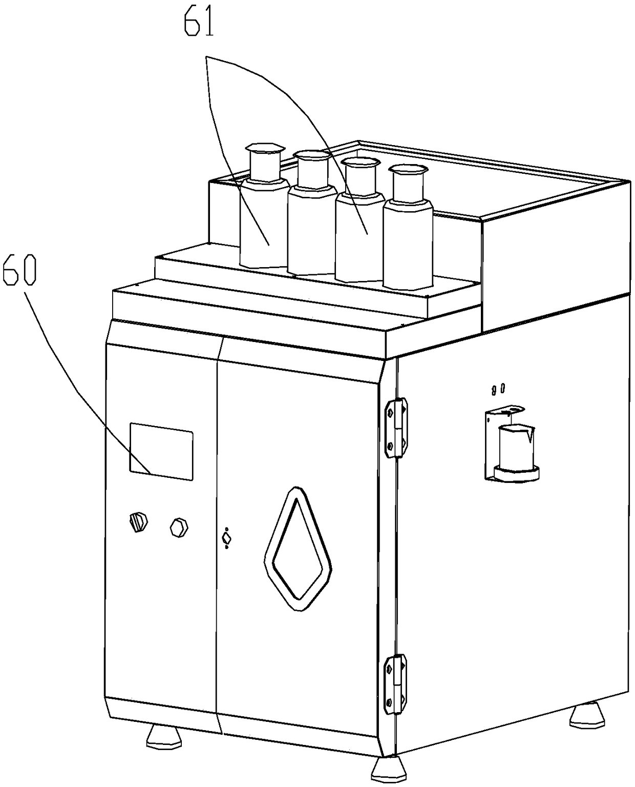
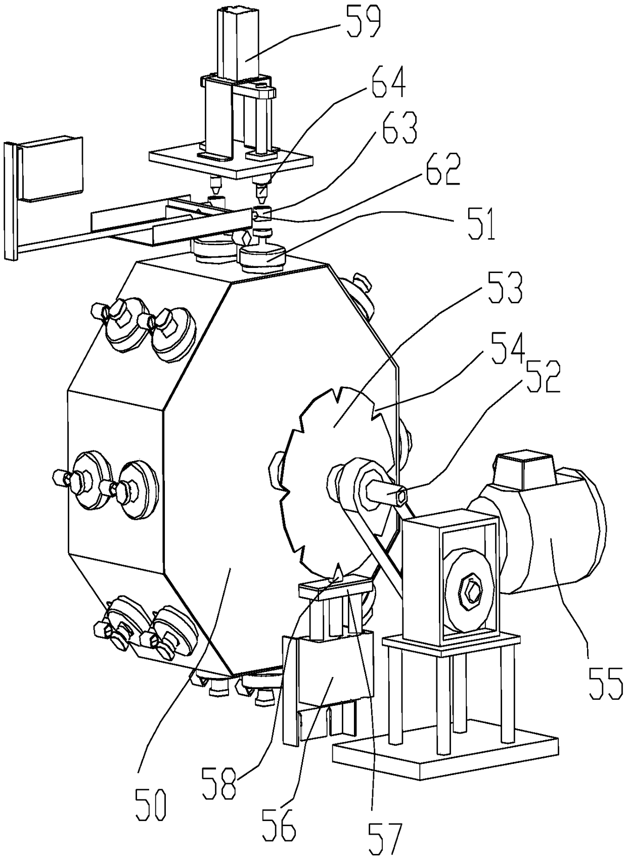
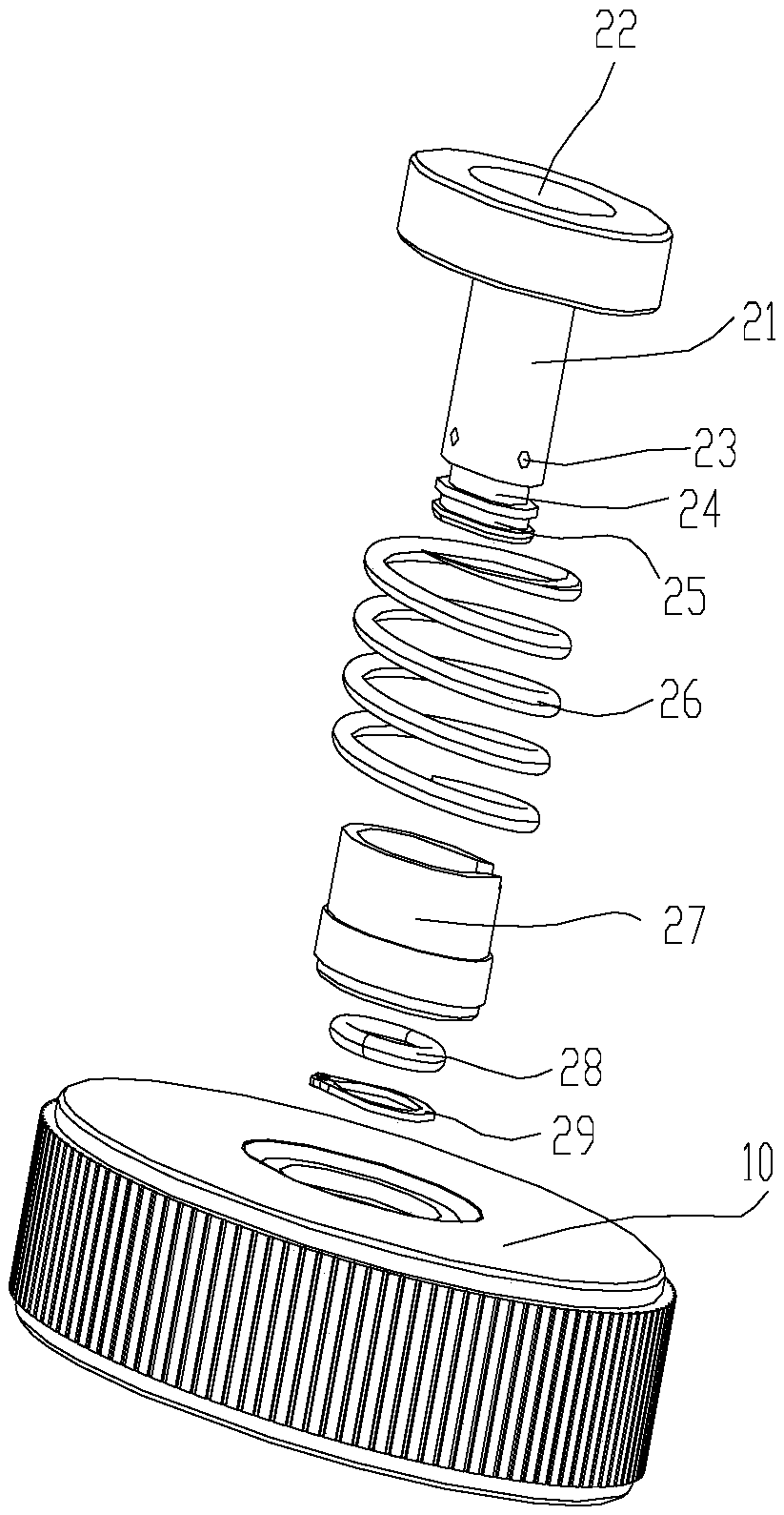
[0044] like Figure 1-7 As shown, an automatic feeding color testing machine includes a housing, a rotating mechanism, a dyeing cup 51, an auxiliary agent adding mechanism and a data processor; The auxiliary agent adding mechanism and the data processor are both arranged in the accommodating cavity. like figure 2 As shown, the rotating mechanism includes a rotating cage 50 and a power mechanism for driving the rotating cage 50 to rotate; the rotating cage 50 is a three-dimensional member formed by regular N-gon stretching, so that the rotating cage is formed with N side walls ; The side wall of the tumbler 50 is provided with at least one inwardly recessed holding tank; the dyeing cup 51 is arranged in the holding tank; as Figure 3-7 As shown, the dyeing cup 51 includes a cup cover, an injection cup and a cup body 46; the cup cover includes a movab...


PUM


Abstract

The invention discloses a color testing machine capable of achieving automatic charging. The color testing machine comprises a shell, a rotating mechanism, dyeing cups, an auxiliary charging mechanism and a data processor; a containing cavity is formed in the shell; the rotating mechanism comprises a rotating cage and a power mechanism, the rotating cage is a three-dimensional component formed by drawing a n-regular polygon, and the side walls of the rotating cage are each provided with internally-concaved containing grooves; the dyeing cups are arranged in the containing grooves; each cup lid comprises a movable shaft which can vertically move, and each movable shaft is provided with a charging port and discharging ports; each material injecting cup is provided with holes and connected with the bottom wall of the corresponding cup lid; cup bodies are connected with the cup lids in a matched mode; when the movable shafts are pressed, the discharging ports of the movable shafts enter the material injecting cups; the auxiliary charging mechanism comprises a flow pump and a first air cylinder, the flow pump is connected with sample charging needles which are opposite to the charging ports, and the first air cylinder is used for pushing the movable shafts; the rotating mechanism and the auxiliary charging mechanism are both controlled by the data processor. According to the color testing machine capable of achieving automatic charging, automatic auxiliary charging is achieved, human errors are reduced, and dyeing defects cannot be generated.

Description

technical field [0001] The invention relates to the technical field of color testing machines, in particular to an automatic feeding color testing machine and a method for using the same. Background technique [0002] Infrared color tester is a small sample color tester, which uses thermal infrared heating to achieve the effect of dyeing, and its performance is stable and reliable. The traditional infrared color testing machine can be roughly divided into two types according to the type of dyed steel cup lid used, and the method of adding additives: [0003] The first one is to use an ordinary dyeing steel cup with a flat lid (that is, an ordinary lid without holes or other accessories). When the dyeing program runs to the time when additives need to be added, it is necessary to suspend the dyeing process, open the machine door, and take out Dye the cup and open the lid, then add the auxiliary agent. This method is cumbersome to operate. It is necessary to weigh the requir...

Claims


Application Information

Patent Timeline
Patent Type & Authority Patents(China)
IPC IPC(8): D06B23/10
CPCD06B23/10
Inventor 黄展湖
Owner 广州市鸿通机械有限公司
Learn More