Supercharge Your Innovation With Domain-Expert AI Agents!

A filling compaction device

A technology of compaction device and road roller, which is applied in the directions of roads, road repair, roads, etc., to achieve the effect of improving turning radius, good off-road performance and stable work

Inactive Publication Date: 2018-01-19
CHANGAN UNIV
View PDF7 Cites 0 Cited by
  • Summary
  • Abstract
  • Description
  • Claims
  • Application Information

AI Technical Summary

Problems solved by technology

[0003] The purpose of the present invention is to provide a filling compaction device to overcome the problems in the prior art. The present invention can make the road roller rotate 360 ​​degrees around the center of mass of the steel wheel, which greatly improves the turning radius of the current road roller.

Method used


Image

  • A filling compaction device
  • A filling compaction device
  • A filling compaction device

Examples


Embodiment Construction

[0024] Below in conjunction with accompanying drawing, the present invention is described in further detail:

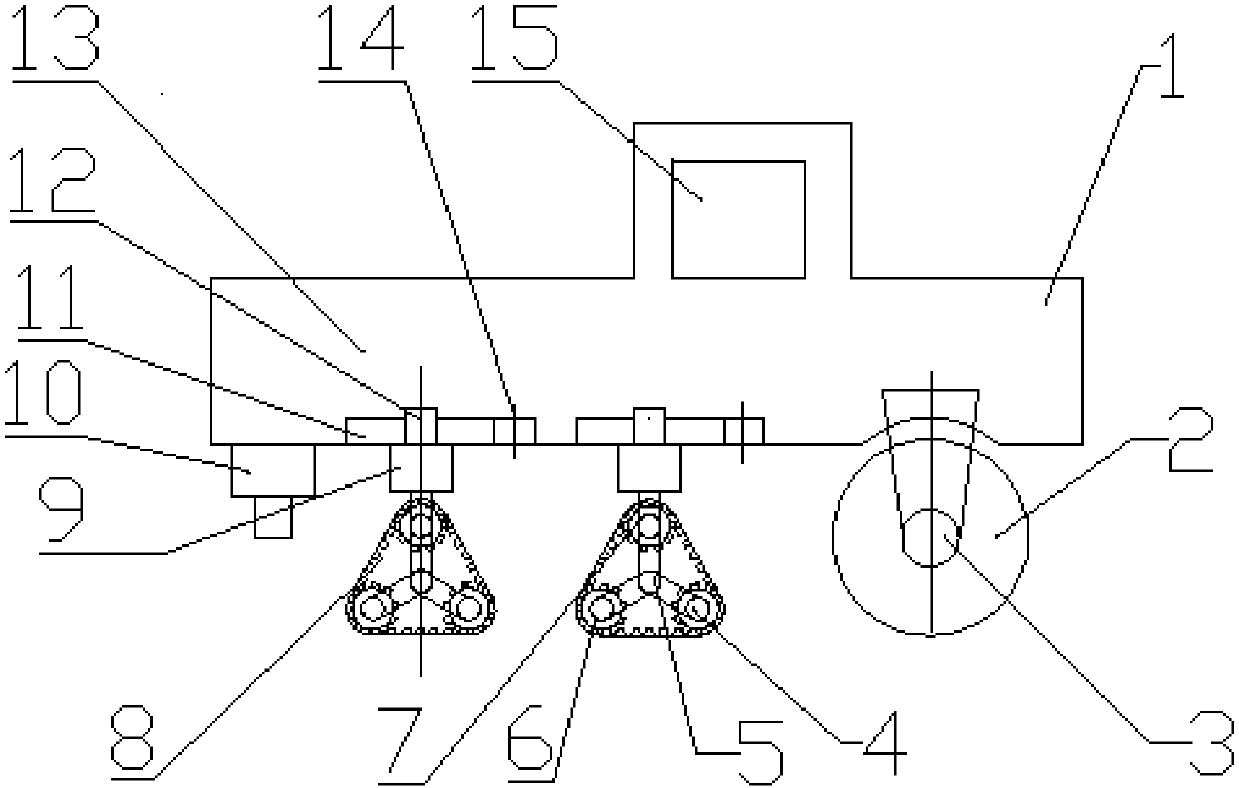
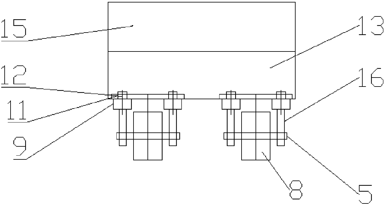
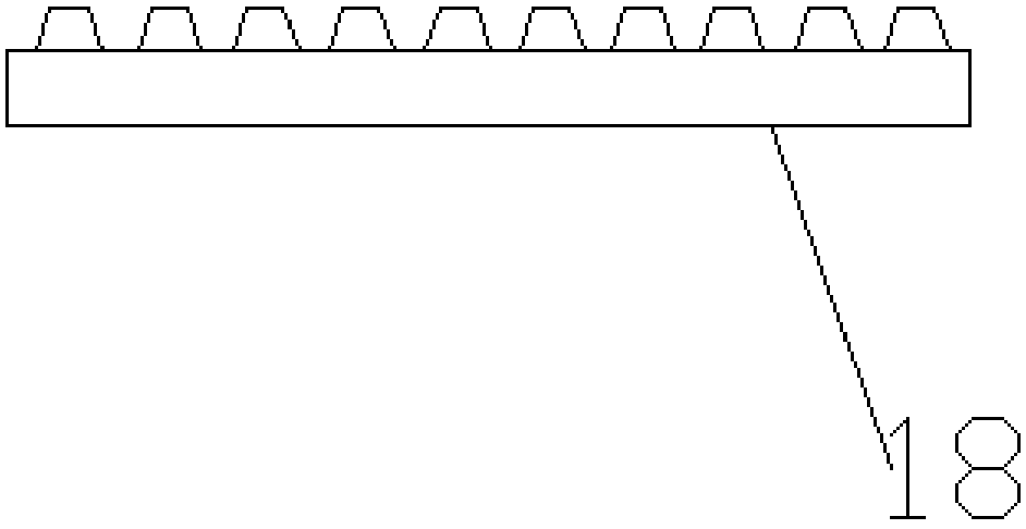
[0025] see Figure 1 to Figure 6 , a filling compaction device, comprising a road roller body 1, a vibrating wheel 2, and a crawler belt device 8, wherein the crawler belt device includes a crawler belt 18 meshed with a driving gear 6 equipped with a hydraulic motor 17, and the driving gear 6 rotates to drive the crawler belt through engagement 18 rotates, and then drives the first driven gear 4 and the second driven gear 7. The road roller body 1 includes a road roller body 13 and a driver's cab 15. There is a hydraulic support 10 at the bottom of the road roller case 13. When the road roller body 1 needs to turn in a wide range, the hydraulic support 10 falls and lands for support, and the crawler belt device 8 is suspended and turns. Landing slowly at the end, the hydraulic support 10 rises off the ground. The height of the crawler device 8 is controlled by the s...


PUM


Abstract

The invention discloses a fill compacting device which comprises a road roller body. A vibration wheel is arranged on the rear side of the bottom of the road roller body. Multiple caterpillar band devices are arranged on the front side of the bottom of the road roller body. Each caterpillar band device comprises a driving gear, a first driven gear and a second driven gear, all of which are triangularly arranged. The outer sides of each driving gear, the corresponding first driven gear and the corresponding second driven gear are provided with a caterpillar band engaged with the driving gear, the first driven gear and the second driven gear. Caterpillar band rotary shafts are arranged at the centers of the caterpillar band devices. Center shafts of each driving gear, the corresponding first driven gear and the corresponding second driven gear are connected with the corresponding caterpillar band rotary shaft through connecting rods. The center shaft of each driving gear is provided with a hydraulic motor. The two ends of each caterpillar band rotary shaft are connected to the road roller body through caterpillar band hydraulic cylinders and self-locking hydraulic cylinders. Each self-locking hydraulic cylinder is connected with a steering device. By the adoption of the fill compacting device, a road roller can rotate by 360 degrees around the mass center of a steel wheel, so that the problem about the turning radius of an existing road roller is greatly solved.

Description

technical field [0001] The invention belongs to the technical field of road machinery, and in particular relates to a filling compaction device. Background technique [0002] Road rollers belong to the category of road equipment in construction machinery. They are widely used in the filling and compaction operations of large-scale engineering projects such as high-grade highways, railways, airport runways, dams, and stadiums. They can roll sandy, semi-cohesive and cohesive soils, Subgrade stabilized soil and asphalt concrete pavement layer. Single-drum vibratory rollers are also widely used in various engineering operations. Most of the current single-drum rollers are tire-type, which often makes them unable to be effectively used in harsh environments. (For example, when the roller is compacting on a gravel road, the undulation of the tire is not conducive to compaction. When compacting on a muddy road, the tire is easy to fall into the swamp.) The limitation of the turnin...

Claims


Application Information

Patent Timeline
Patent Type & Authority Patents(China)
IPC IPC(8): E01C19/28
CPCE01C19/28E01C19/286
Inventor 张晓波侯劲汝郭健王慧强
Owner CHANGAN UNIV
Features
  • R&D
  • Intellectual Property
  • Life Sciences
  • Materials
  • Tech Scout
  • Unparalleled Data Quality
  • Higher Quality Content
  • 60% Fewer Hallucinations
Learn More