The hydraulic connection structure connecting the crosshead body and the piston rod

A technology of crosshead body and connection structure, which is applied in the direction of crosshead, liquid displacement machinery, variable displacement pump components, etc. It can solve the problems of one side deviation of the drill bit, troublesome repair of parts, replacement of new tooling, etc., and achieve saving Materials, simple processing, and the effect of ensuring processing quality and precision

Inactive Publication Date: 2017-11-17
沈阳佳信压缩机制造有限公司
View PDF9 Cites 5 Cited by
  • Summary
  • Abstract
  • Description
  • Claims
  • Application Information

AI Technical Summary

Problems solved by technology

[0012] The oil hole of the existing crosshead body is eccentric structure, the drill bit is easy to deviate to one side during drilling, and it is easy to damage the drill bit, so a false crosshead pin tooling must be installed to prevent the drill bit from deviation during drilling. It is both troublesome and must be replaced with new tooling from time to time
[0013] When the original structure is being processed, once the size of the key on the crosshead body is out of tolerance or the size of the keyway of the sliding shoe is out of tolerance, it will be very troublesome to repair any part to the size specified in the drawing.

Method used


Image

  • The hydraulic connection structure connecting the crosshead body and the piston rod
  • The hydraulic connection structure connecting the crosshead body and the piston rod
  • The hydraulic connection structure connecting the crosshead body and the piston rod

Examples


Embodiment Construction

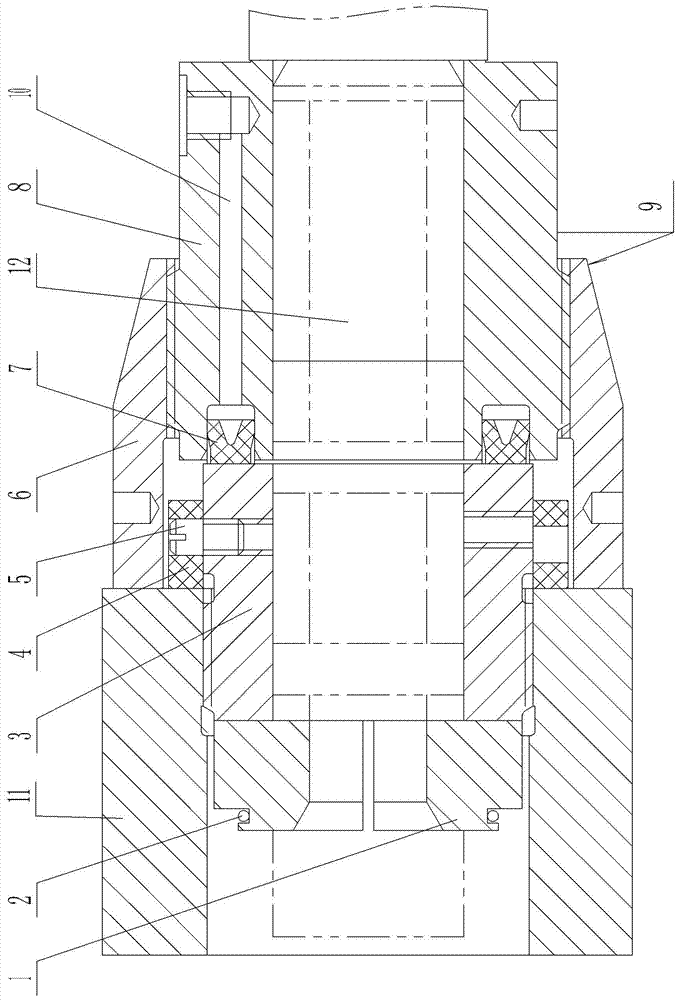
[0043] As shown in the figure, the present invention includes a crosshead body and a piston rod. One end of the piston rod is placed in the crosshead body, and a thrust ring is arranged at the rear end of the piston rod placed in the crosshead body. A screw-in ring is provided, the front part of the outer ring of the screw-in ring is threadedly connected with the inner wall of the crosshead, the rear part of the screw-in ring is placed outside the crosshead body, and a pressure body is arranged on the periphery of the piston rod at the rear end of the screw-in ring, and the outer wall of the front part of the pressure body It is threadedly connected with the rear part of the fastening nut, and the front end of the fastening nut is connected with the end surface of the crosshead body; the rear end of the pressure body is provided with a vertical pressing hole, the lower part of the vertical pressing hole is connected with one end of the horizontal pressing hole, and the other end...


PUM


Abstract

The invention provides a hydraulic connection structure for connecting a crosshead body with a piston rod and belongs to the technical field of connection structures of crosshead bodies and piston rods. The hydraulic connection structure for connecting the crosshead body with the piston rod is simple in structure, good in connection effect and high in safety coefficient. The hydraulic connection structure comprises the crosshead body and the piston rod, one end of the piston rod is arranged in the crosshead body, the rear end of the end head, arranged in the crosshead body, of the piston rod is provided with a thrust ring, the outer periphery, at the rear end of the thrust ring, of the piston rod is provided with a screwing-in ring, the front of an outer ring of the screwing-in ring is in threaded connection with the inner wall of the crosshead body, the rear portion of the screwing-in ring is arranged outside the crosshead body, the outer periphery, at the rear end of the screwing-in ring, of the piston rod is provided with a pressure body, the outer wall of the front of the pressure body is in threaded connection with the rear portion of a tightening nut, and front end of the tightening nut is connected with the end face of the crosshead body.

Description

technical field [0001] The invention belongs to the technical field of connection structure between a crosshead body and a piston rod, and in particular relates to a hydraulic connection structure for connecting a crosshead body and a piston rod. Background technique [0002] Such as Figure 4 As shown, after the gap between the dead centers of the piston is adjusted, if the positioning ring 107 and the end surface of the crosshead 11 are fitted together, they are just fitted together, and there is no compression state. After pressing 150MPa, it will definitely not fit together, and it will be in a gap state. After the dead point gap is adjusted, there is a gap. In order to ensure the accuracy of the adjustment of the stop gap, the two surfaces are in a state of gap in most cases, and the state of being fitted together is rare. If it is necessary to ensure that the positioning ring and the crosshead fit together, the accuracy of the dead center gap of the piston cannot be g...

Claims


Application Information

Patent Timeline
Patent Type & Authority Patents(China)
IPC IPC(8): F04B39/00F16C5/00
CPCF04B39/00F16C5/00
Inventor 邙铁宏郭永君
Owner 沈阳佳信压缩机制造有限公司
Why Eureka
Try Eureka