Cross plate shearing apparatus

A technology of shearing device and cross shearing plate, applied in measuring device, using stable shearing force to test the strength of materials, instruments, etc., can solve the problems of inability to be very accurate, low precision, and high insulation requirements

Inactive Publication Date: 2016-09-28
HOHAI UNIV
View PDF5 Cites 5 Cited by
  • Summary
  • Abstract
  • Description
  • Claims
  • Application Information

AI Technical Summary

Problems solved by technology

The mechanical cross-plate instrument can automatically collect data, but it has high requirements for meteorological conditions and probe insulation, and the operation is cumbersome and the accuracy is not high, and the friction of the shaft needs to be corrected.
The electric measuring cross plate instrument does not need the correction of the shaft friction force, does not drill holes, has the characteristics of continuous and rapid and high test accuracy, but has high requirements for meteorological conditions and obvious artificial interference factors
The basic principle of the cross-plate shear test is to calculate the in-situ shear strength by using the magnitude of the applied torque during shear failure, and because the two bottom surfaces of the traditional cross plate shear failure in the radial direction at different times , so what we get is an average value, not a peak value, so this brings observation error to the analysis critical failure point
In addition, the existing cross-shear device mainly uses the bubble center of the level to correct the level, and manual judgment is used, which can neither be very accurate nor real-time adjustment

Method used


Image

  • Cross plate shearing apparatus
  • Cross plate shearing apparatus
  • Cross plate shearing apparatus

Examples


Embodiment 1

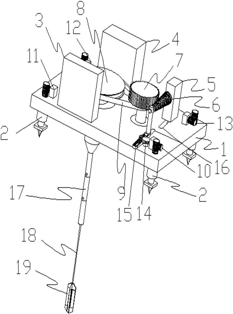
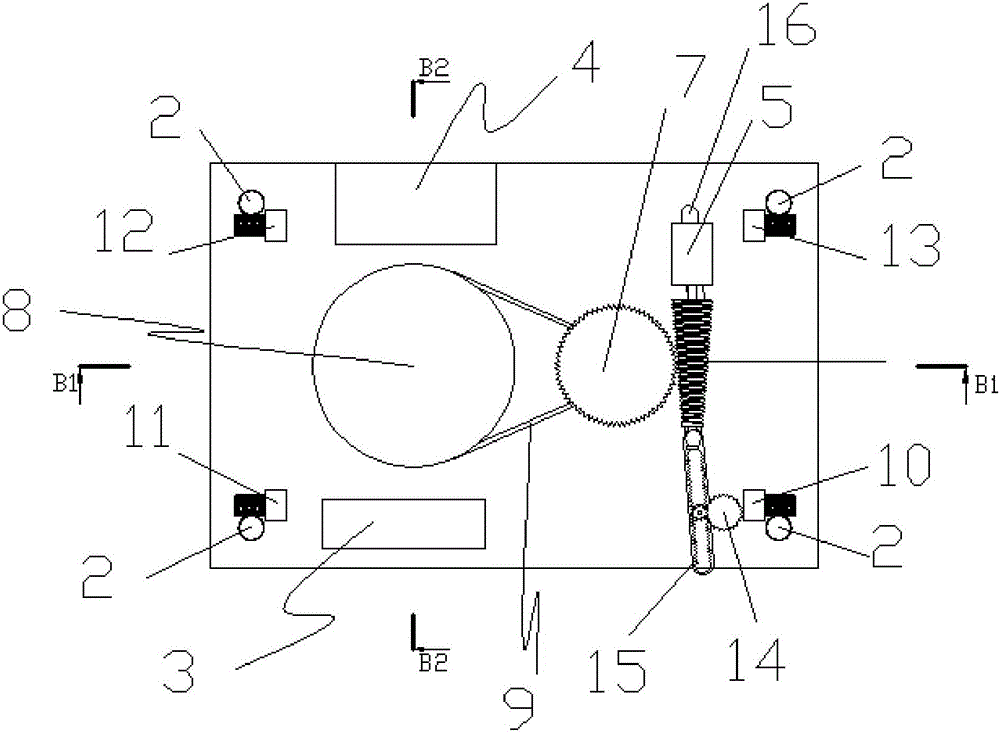
[0070] Such as figure 1 with figure 2 Shown: a cross plate shearing device, including a bottom plate 1 as a loading device platform, support feet 2 around the bottom plate 1, a console 3 and a power supply box 4 on the bottom plate 1.

[0071] The loading device includes a motor 5, a conical wheel 6, a driven wheel structure 7, a runner structure 8, a transmission belt 9 and a stepping motor 5 14. The supporting feet 2 corresponding to the surroundings on the base plate 1 have stepping motor one 10, stepping motor two 11, stepping motor three 12, and stepping motor four 13 to automatically adjust the height of the supporting feet 2 to keep the level.

[0072] The drill rod 17 can be lengthened by connecting many standard long drill rod sections, and the drill rod 17 is connected with the runner structure 8 and the cross plate shear plate axle rod 18 as a force transmission member.

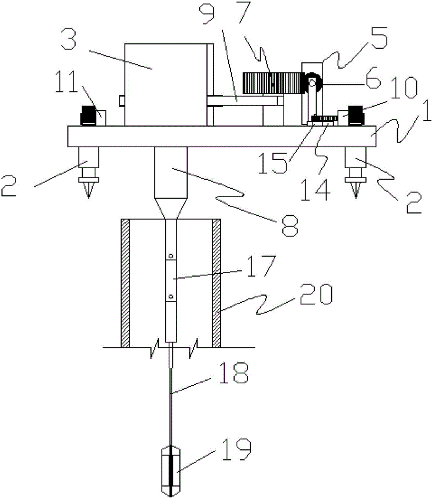
[0073] Such as image 3 As shown, the sleeve 20 is added in the embodiment, and the sleeve ...

Embodiment 2

[0099] In embodiment 2, only the novel cross shear plate device in embodiment 1 is changed, and changes are as follows:

[0100] The new cross shear plate consists of: cross plate shear plate shaft rod 18, fixed blade 53, cross plate 19, one-way bearing 34 and shaft sleeve 55, cross plate shear plate shaft rod 18 is connected with the drill pipe, as Figure 6 shown. A fixed vane 53 is installed on the cross plate shear plate shaft 18, and a one-way bearing is placed between the fixed vane 53 and the cross plate shear plate shaft 18, that is, the top cross plate correction plate 35 of the shaft bar and the cross plate correction plate 35 at the bottom of the shaft bar. A one-way bearing is also used between the plate 36 and the shaft 18 . Such as Figure 15 with Figure 41 As shown, the cross plate shear plate shaft rod 18 is inserted in the shaft sleeve 55 of the cross plate 19, as Figure 15 , Figure 18 with Figure 19 As shown, three one-way bearings 34 are equidistan...


PUM

PropertyMeasurementUnit
thicknessaaaaaaaaaa

Abstract

The invention relates to a cross plate shearing apparatus, and belongs to the an engineering test apparatus used for in situ shearing of soil layer test. The baseboard of the cross plate shearing apparatus is provided with a control bench and a power supply box; a power device is arranged on the baseboard, and the bottom end of the baseboard is supported by supporting legs; the bottom of the power device is connected with a drilling rod, and the drilling rod is formed through connecting a plurality of drilling rod segments; the lower end of the drilling rod is provided with a cross shearing plate shaft lever, and the bottom end of the cross shearing plate shaft lever is provided with a cross plate; the power device drives the cross shearing plate shaft lever to rotate; the supporting legs can adjust the levelness of the baseboard; and the power supply box supplies power to the power device and the control bench, and the control bench controls the power device and the supporting legs. The cross plate shearing apparatus is a mechanical apparatus executing a balance instruction based on gyroscope measured level feedback, is a mechanical apparatus being able to provide multiple speed reduction and to carry out low-speed accurate control based on a common motor, is a measured force feedback apparatus based on a piezoelectric sensing element, and is a cross shearing apparatus for obtaining soil layer shearing destroy intensity peak data.

Description

technical field [0001] The invention relates to a cross-plate shearing device, belonging to an engineering test device for in-situ shearing soil layer tests. Background technique [0002] The cross-plate shear test has been widely used to measure the shear strength of saturated soft cohesive soil, and it is an indispensable in-situ test method for calculation of foundation mechanical parameters such as foundation bearing capacity, embankment stability, soft clay sensitivity and consolidation history . The cross plate shear test includes indoor test and outdoor in situ test, usually using a micro cross plate instrument. Indoor test determination needs to go through sampling, transportation, sample cutting and other processes, which often cause disturbance to the soil sample, especially the high thixotropy of saturated soft clay, which makes the soil structure very easy to be destroyed during the sampling process , in addition, it is also susceptible to greater interference ...

Claims


Application Information

Patent Timeline
Patent Type & Authority Applications(China)
IPC IPC(8): G01N3/24
CPCG01N3/24G01N2203/005
Inventor 郭瑞李同春林潮宁林川宁昕扬
Owner HOHAI UNIV
Why Eureka
Try Eureka