Method for realizing beam tight focusing through vortex beams

A vortex beam, tight focusing technology, applied in optics, optical components, instruments, etc., can solve the problem of focusing spot numerical aperture and light wavelength limitation that cannot obtain focusing effect, etc.

Inactive Publication Date: 2016-09-28
HARBIN INST OF TECH
View PDF2 Cites 24 Cited by
  • Summary
  • Abstract
  • Description
  • Claims
  • Application Information

AI Technical Summary

Problems solved by technology

[0003] The purpose of the present invention is to solve the problem that the size of the focusing spot in the prior art is limited by the numerical aperture and the light wavelength and cannot obtain a focusing effect better than the Rayleigh diffraction limit, and proposes a method of using a vortex beam to achieve a tight focus of the beam

Method used


Image

  • Method for realizing beam tight focusing through vortex beams
  • Method for realizing beam tight focusing through vortex beams
  • Method for realizing beam tight focusing through vortex beams

Examples


specific Embodiment approach 1

[0026] Specific Embodiment 1: A method of using a vortex beam to achieve tight beam focusing in this embodiment is specifically prepared according to the following steps:

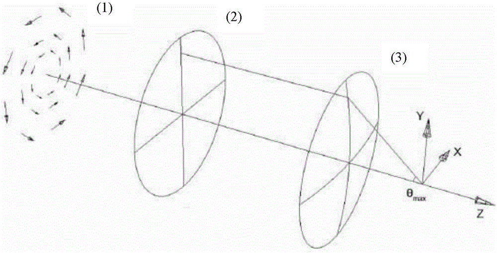
[0027] The device for realizing tight focusing of beams by using vortex beams specifically includes an azimuthal polarizer, a 0-2π spiral phase plate (VPP-1c) and a high numerical aperture focusing lens such as figure 1 (GCL-010213);

[0028] Step 1, making the azimuthal polarized light incident on the helical phase plate;

[0029] Step 2, using the spiral phase plate to linearly modulate the phase of the azimuthally polarized light according to the angular orientation in the range of 0 to 2π, thereby completing spatial phase encoding to form a vortex beam;

[0030] Step 3. Let the vortex beam with known phase encoding pass through the aperture focusing lens to form a focused spot that is better than the Rayleigh diffraction limit;

[0031] The general idea is that polarized light and phase-encoded light...

specific Embodiment approach 2

[0053] Specific embodiment 2: The difference between this embodiment and specific embodiment 1 is that in step 2, the phase of azimuthally polarized light is controlled by a spiral phase plate in the angular direction Linear modulation is performed in the interval. Other steps and parameters are the same as those in Embodiment 1.

specific Embodiment approach 3

[0054] Embodiment 3: The difference between this embodiment and Embodiment 1 or 2 is that the specific process of phase encoding in step 2 to form a vortex beam is as follows:

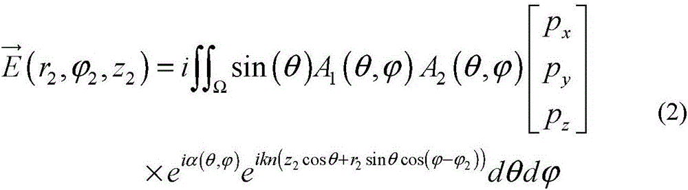
[0055] The electric vector of incident azimuthally polarized light is After passing through the spiral phase plate, the electric vector for:

[0056]

[0057] In the formula: is the azimuth coordinate function; e is the exponential function;

[0058] From the above formula, it can be seen that the phase distribution on the cross-section of the beam changes with the radial angle, which has vortex characteristics; making azimuthally polarized light into a vortex beam. Other steps and parameters are the same as those in Embodiment 1 or Embodiment 2.


PUM


Abstract

The invention provides a method for realizing beam tight focusing through vortex beams, relates to the method for beam tight focusing, and provides the method for realizing beam tight focusing through the vortex beams for solving the problems in the prior art that the aperture of an optical system is limited by the size of equipment and the focusing effect better than the Rayleigh diffraction limit cannot be acquired. The method is realized by the steps that firstly azimuth polarized light is incident to a spiral phase plate; secondly, the phase of the azimuth polarized light is linearly modulated according to the annular azimuth of being within the interval of 0-2pi by utilizing the spiral phase plate so that spatial phase coding is completed and the vortex beams are formed; and thirdly the vortex beams of the known phase code are enabled to pass through a focusing lens of high value aperture so that focusing light spots better than the Rayleigh diffraction limit are formed. The method for realizing beam tight focusing through the vortex beams is suitable for the field of beam tight focusing and super-resolution imaging.

Description

technical field [0001] The invention relates to a method for realizing tight focusing of light beams by using vortex light beams. Background technique [0002] Tight beam focusing has extremely high application value in optical data storage, lithography, and super-resolution imaging. Current optical focusing methods are limited by the classical diffraction limit. Under this limit, the spot size of the focused beam has a minimum value, with a radius of 0.61λ 2 / D. Where λ is the wavelength of light, and D is the numerical aperture of the optical system. It can be seen from the formula that to obtain a smaller spot needs to increase the numerical aperture or decrease the wavelength. In practical applications, both the numerical aperture and the wavelength are limited, and the numerical aperture cannot be increased or the wavelength can be reduced infinitely. How to obtain a smaller spot under the condition of a certain numerical aperture and wavelength has become an urgent...

Claims


Application Information

Patent Timeline
IPC IPC(8): G02B27/58G02B27/28
CPCG02B27/286G02B27/58
Inventor 张子静赵远马昆苏建忠王峰
Owner HARBIN INST OF TECH
Why Eureka
Try Eureka