Real beam scanning radar front-view super-resolution imaging method

A scanning radar and super-resolution technology, applied in radio wave measurement system, radio wave reflection/re-radiation, using re-radiation, etc., can solve problems such as edge blur

Active Publication Date: 2017-06-30
CHINA ELECTRONIC TECH GRP CORP NO 38 RES INST
View PDF3 Cites 30 Cited by
  • Summary
  • Abstract
  • Description
  • Claims
  • Application Information

AI Technical Summary

Problems solved by technology

[0006] In order to solve the technical problem of blurred edges in surface target radar angle super-resolution imaging, the present invention provides a real-beam scanning radar front-view super-resolution imaging method

Method used


Image

  • Real beam scanning radar front-view super-resolution imaging method
  • Real beam scanning radar front-view super-resolution imaging method
  • Real beam scanning radar front-view super-resolution imaging method

Examples


Embodiment 1

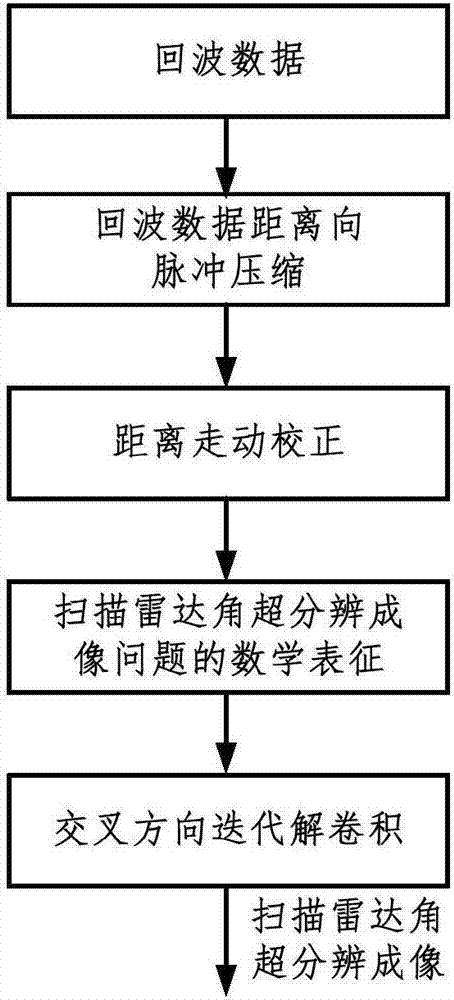
[0095] The present invention uses simulation experiments to demonstrate the feasibility and effectiveness of the proposed radar angle super-resolution imaging method. see figure 1 , all steps of the present invention, conclusion are verified correctly on Matlab2012 emulation platform, provide the detailed operation step of implementing the inventive method below.

[0096] Step 1: Forward-looking scanning radar echo modeling

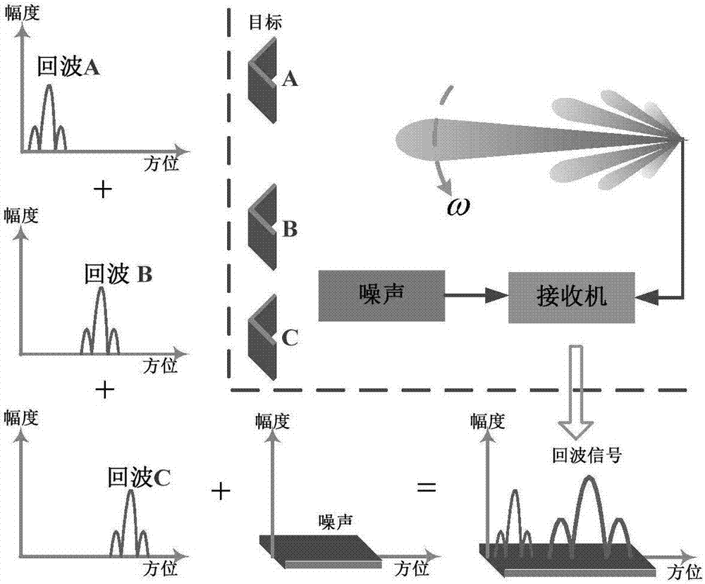
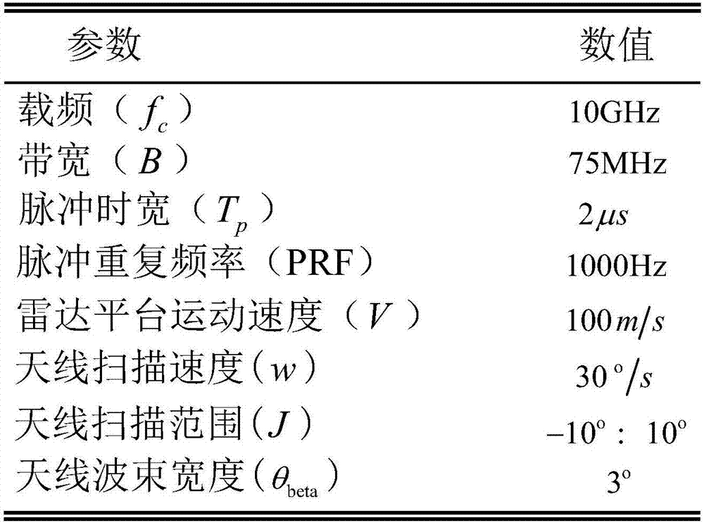
[0097] This implementation adopts the forward-looking scanning radar imaging motion geometry mode, and the top view of the antenna beam sweeping the imaging area, as shown in the attached figure 2 shown. Scanning radar system parameters are attached image 3 shown. The simulation scenarios used in the steps of this program are attached Figure 5 shown. There are differences in the simulation target angle and amplitude settings, and surface targets with edge characteristics are also set between the targets. This is to reflect that the method provide...

Embodiment 2

[0127] Aiming at the technical defects of the deconvolution method introduced in the background technology in realizing super-resolution imaging of surface target angles, the present invention proposes a solution that uses the total variation functional of target reflectivity in the imaging area to represent the prior information of surface target scattering convolution method. This method not only breaks through the difficulty of mathematical representation of surface object edge scattering prior information, but also avoids the calculation amount caused by the selection of regularization parameters in the convolution process. Using the method disclosed in the invention to perform radar angle super-resolution imaging on surface targets effectively solves the problem of blurred edges when imaging surface targets.

[0128] The solution of the present invention is to model the scanning radar azimuth echo as the linear convolution of the azimuth sampling sequence of the target re...


PUM


Abstract

The invention discloses a real beam scanning radar front-view super-resolution imaging method, which belongs to a method for realizing scanning radar front-view super-resolution imaging by using the total variation functional of the scattering coefficient of an imaging region as de-convolution of priori information. A scanning radar azimuth echo signal is modeled into a result obtained by superimposing noise onto the convolution of a sampling sequence of antenna beam along the azimuth and a sampling sequence of a target reflectance distribution function along the azimuth, and a problem of scanning radar front-view super-resolution imaging is converted into a de-convolution problem; then, the total variation functional of the scattering coefficient of an imaging region is integrated into priori information of the de-convolution problem, and the de-convolution problem is converted into a constrained optimization problem; and finally, a global optimal solution to the constrained optimization problem is obtained through a cross iteration method, and scanning radar front-view super-resolution imaging is realized.

Description

technical field [0001] The invention relates to an imaging method, in particular to a real-beam scanning radar front view super-resolution imaging method. Background technique [0002] The two-dimensional high-resolution imaging of the forward-looking area of ​​the radar platform has urgent application requirements in the fields of ground search, sea detection and imaging, aircraft blind landing, terrain matching, terrain following, ground attack, and missile terminal guidance. [0003] Both the synthetic aperture radar imaging method and the Doppler beam sharpening technology can achieve high-resolution imaging. Due to the constraints of the imaging mechanism, these two methods are not suitable for high-resolution imaging in the forward-looking area of ​​the radar platform. The real beam scanning radar integrates the prior information of the target scattering in space according to the time sequence of the antenna beam passing over the imaging scene, and uses mathematical ca...

Claims


Application Information

Patent Timeline
Patent Type & Authority Applications(China)
IPC IPC(8): G01S13/89G01S7/292G01S7/41
CPCG01S7/292G01S7/41G01S13/89
Inventor 查月波罗健沙祥王月刘露
Owner CHINA ELECTRONIC TECH GRP CORP NO 38 RES INST
Why Eureka
Try Eureka