Spring wire brush and electric slip ring used

An electric slip ring and electric brush technology, applied in the field of electric slip rings, can solve the problems such as the number of input and output wires that cannot be expanded, the length cannot be lengthened, and the structure is complicated, and the assembly is fast and efficient, and the structure is simplified. Easy to assemble and efficient effect

Active Publication Date: 2018-11-09
杭州摇头龙科技有限公司
View PDF8 Cites 0 Cited by
  • Summary
  • Abstract
  • Description
  • Claims
  • Application Information

AI Technical Summary

Problems solved by technology

The collector ring of this structure has the following defects: first, the structure is complex, the carbon brush needs to be installed in the carbon brush sleeve, and the spring top pressure is required; second, the wear is fast, and the carbon brush needs to be replaced frequently; third, there are hidden dangers, carbon Toner powder generated by brush wear can easily cause short circuits
[0003] In order to overcome the defects of the above-mentioned prior art, the Chinese invention application (application number 201310315647.9) discloses an "underwater elastic wire collector ring", which is fixed with an elastic metal wire on the insulating block. One end of the wire is pressed against the outer circular surface of the metal ring, and the other end is connected to the wire on the stator. Although this structure is simpler and wear-resistant than traditional carbon brushes, the insulating card arranged on the stator 9 Once the block 3 is formed, its axial length cannot be lengthened, and the number of metal wires 4 installed on it is limited, so it is impossible to expand the number of input and output wires (including power lines and control lines) of the slip ring

Method used


Image

  • Spring wire brush and electric slip ring used
  • Spring wire brush and electric slip ring used
  • Spring wire brush and electric slip ring used

Examples


Embodiment Construction

[0024] In order to make the technical solution of the present invention clearer, the following in conjunction with the attached Figures 1 to 10 , the present invention will be described in detail. It should be understood that the specific implementations described in this specification are only for explaining the present invention, and are not intended to limit the protection scope of the present invention.

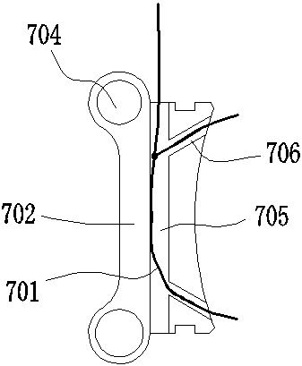
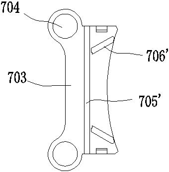
[0025] The invention relates to a spring wire electric brush and an electric slip ring for matching use.

[0026] The spring wire brush (7) includes the electric card (702) and the electric card cover (703) which are fastened together, and the metal spring wire (701) is sandwiched between the electric card (702) and the electric card cover (703). At least one metal elastic wire (701) is drawn out from the inner end of the elastic wire brush (7), and at least one is provided at the outer end of the elastic wire brush (7) for passing through a stay ( 803) for brush pierc...


PUM


Abstract

The invention discloses an elastic filament brush and a matched electric slip ring. The elastic filament brush comprises an electric brush clip and an electric brush clip cover, which are buckled together. A metal elastic filament is clamped between the electric brush clip and the electric brush clip cover. An inner end of the elastic filament brush is provided with at least one metal elastic filament which is led out, and an outer end of the elastic filament brush is provided with at least one electric brush perforation which is used for the passing of a supporting bar. The electric slip ring matched with the elastic filament brush is formed by the alternate stacking of copper rings and copper ring spacers. The upper surface of each copper ring spacer is provided with an upper annular convex edge for the positioning of the corresponding copper ring, and the lower surface of each copper ring spacer is provided with a lower annular convex edge for the positioning of the corresponding copper ring. According to the invention, the elastic filament brush and the matched electric slip ring are simple in structure, and are resistant to wear. Moreover, the number of input / output conductors of a collector ring formed by the elastic filament brush and the matched electric slip ring can be increased flexibly, thereby meeting different needs.

Description

technical field [0001] The invention relates to a spring wire electric brush and an electric slip ring used in conjunction with it. Background technique [0002] Traditional collector rings are mainly composed of copper rings and carbon brushes pressed against the outer surface of the copper rings. The collector ring of this structure has the following defects: first, the structure is complex, the carbon brush needs to be installed in the carbon brush sleeve, and the spring top pressure is required; second, the wear is fast, and the carbon brush needs to be replaced frequently; third, there are hidden dangers, carbon Toner dust from brush wear can easily cause short circuits. [0003] In order to overcome the defects of the above-mentioned prior art, the Chinese invention application (application number 201310315647.9) discloses an "Underwater Elastic Wire Collector Ring", which is fixed with an elastic metal wire on the insulating block. One end of the wire is pressed aga...

Claims


Application Information

Patent Timeline
Patent Type & Authority Patents(China)
IPC IPC(8): H01R39/02H01R39/08H01R39/24H01R39/64
CPCH01R39/02H01R39/08H01R39/24H01R39/64
Inventor 许杭旭彭长慧孟元黔
Owner 杭州摇头龙科技有限公司
Why Eureka
Try Eureka