Multi-inverter active power control method for photovoltaic power station

A photovoltaic power station, active power technology, applied in the direction of photovoltaic power generation, electrical components, circuit devices, etc. Transformer response characteristics and other issues

Active Publication Date: 2018-07-24
TIANJIN UNIV
View PDF2 Cites 0 Cited by
  • Summary
  • Abstract
  • Description
  • Claims
  • Application Information

AI Technical Summary

Problems solved by technology

At present, the active power control strategy of the photovoltaic power station implements unified adjustment of the inverter during the power distribution process, and handles the power regulation task of the photovoltaic power station in a simple and average distribution method, without considering the response characteristics of the photovoltaic inverter in the photovoltaic power station. difference, and there is no literature on power distribution research on the difference in response characteristics of photovoltaic inverters
However, in the actual photovoltaic power station, due to the influence of factors such as the construction period of the photovoltaic power station and the manufacturer and product model of the photovoltaic inverter, there are differences in the response characteristics of the inverter, which makes the active power regulation speed of the inverter in the photovoltaic power station Different, some inverters can respond quickly to active power regulation commands, while others respond slowly
If only a simple average distribution method is used to deal with the power regulation problem of the photovoltaic power station, it will inevitably make the adjustment time of active power too long, which will lead to the slowdown of the overall active power regulation speed of the photovoltaic power station

Method used


Image

  • Multi-inverter active power control method for photovoltaic power station
  • Multi-inverter active power control method for photovoltaic power station
  • Multi-inverter active power control method for photovoltaic power station

Examples


Embodiment Construction

[0041] The technical solution of the invention will be described in detail below in conjunction with the embodiments and with reference to the accompanying drawings.

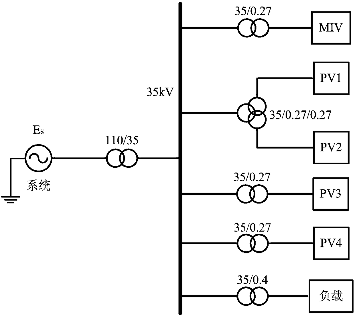
[0042] This embodiment takes figure 1 The topological diagram of the grid-connected power generation system of the photovoltaic power station is shown as an example. In the figure, there is one model inverter MIV, one slow-response inverter, and three fast-response inverters.

[0043] (1) The photovoltaic power station operation manufacturer specifies an inverter with stable operation performance and fast response speed as the model inverter MIV through the station operation data or product parameters. The MIV always works in the maximum power mode, and the output power Intensity is related to temperature, does not receive power adjustment commands, that is, outputs active power but does not participate in active power adjustment; figure 1 Middle MIV is a model inverter. MIV maximum operating power P miv_max ...


PUM


Abstract

The invention relates to a control method of multi-inverter power output for a photovoltaic power station. The method comprises the following steps: determining a sample inverter by an operation factory so as to determine an upper limit and a lower limit of each inverter output power; dividing the inverters into slow response inverters and fast response inverters according to the response speed, and only performing operation on the fast inverters; setting an upper limit judgment loop of an active power scheduling instruction, and modifying the active power scheduling instruction; setting a power regulating dead area judgment loop; setting a power balance mechanism, and firstly enabling the fast response inverters to mainly bear the power regulating task when the regulating instruction is changed, so that the output power of the photovoltaic power station fast approaches to the regulating instruction; and meanwhile, regulating the slow inverters using the power reference value which is same as that of the fast inverters; and dynamically balancing the power regulating tack between two types of inverters. Through the adoption of the method disclosed by the invention, the active power output of the photovoltaic power station can be fast and accurately regulated, and the method is capable of responding to the subsequent adjusting task.

Description

technical field [0001] The invention belongs to the technical field of new energy photovoltaic power generation and grid dispatching, and is a control method capable of realizing rapid and accurate adjustment of active power output of a photovoltaic power station. Background technique [0002] In recent years, the development and utilization of new energy represented by photovoltaic and wind power has attracted more and more attention from various countries. Photovoltaic power generation is constrained by solar energy resources, and has the characteristics of randomness, intermittent, periodicity and volatility. With the rapid growth of installed capacity of photovoltaic power stations, its impact on the power system is also increasing. In order to reduce the impact of large-scale photovoltaic grid-connection on the power grid, the State Grid Corporation of China issued the "Technical Regulations for Photovoltaic Power Stations Connected to the Grid" in May 2011, which stipu...

Claims


Application Information

Patent Timeline
Patent Type & Authority Patents(China)
IPC IPC(8): H02J3/48
CPCH02J3/383H02J3/48Y02E10/56Y02P80/20
Inventor 李永丽马立凡常晓勇
Owner TIANJIN UNIV
Why Eureka
Try Eureka