
Segmented cage and roller bearing

A technology of roller bearings and cages, applied in the direction of roller bearings, shafts and bearings, rolling contact bearings, etc., to achieve the effect of preventing damage

Inactive Publication Date: 2016-09-28
JTEKT CORP
View PDF16 Cites 0 Cited by
  • Summary
  • Abstract
  • Description
  • Claims
  • Application Information

AI Technical Summary

Problems solved by technology

The edge portions 92 and 92 are separated from each other at a predetermined interval in the axial direction so as to face each other

Method used


Image

  • Segmented cage and roller bearing
  • Segmented cage and roller bearing
  • Segmented cage and roller bearing

Examples


Embodiment Construction

[0078] Embodiments of the present invention will be described below with reference to the drawings.

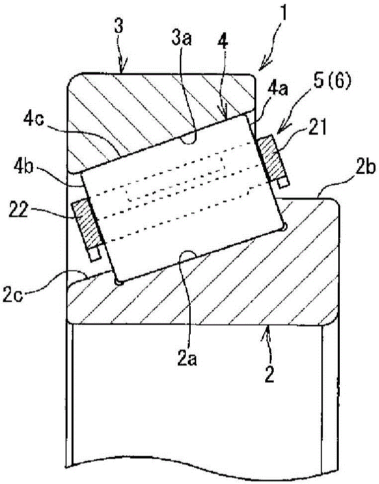
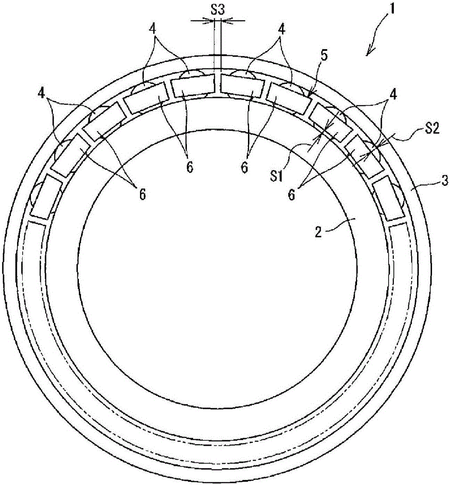
[0079] figure 1 is a main part sectional view showing a roller bearing provided with a cage according to the present invention. figure 2 is a side view showing the roller bearing. The roller bearing 1 according to this embodiment is a tapered roller bearing comprising an inner ring 2, an outer ring 3, a plurality of tapered rollers rollably arranged in an annular space between the inner ring 2 and the outer ring 3 4 and the cage 5 holding the tapered roller 4. The cage 5 according to this embodiment is a divided cage having a plurality of cage segments 6 . The inner ring 2, the outer ring 3 and the tapered rollers 4 are made of steel such as bearing steel.

[0080] exist figure 1 Among them, in the inner periphery of the outer ring 3, an outer ring raceway surface 3a made of a tapered surface is formed so that the tapered rollers 4 can roll on the outer ring raceway surf...


PUM


Abstract

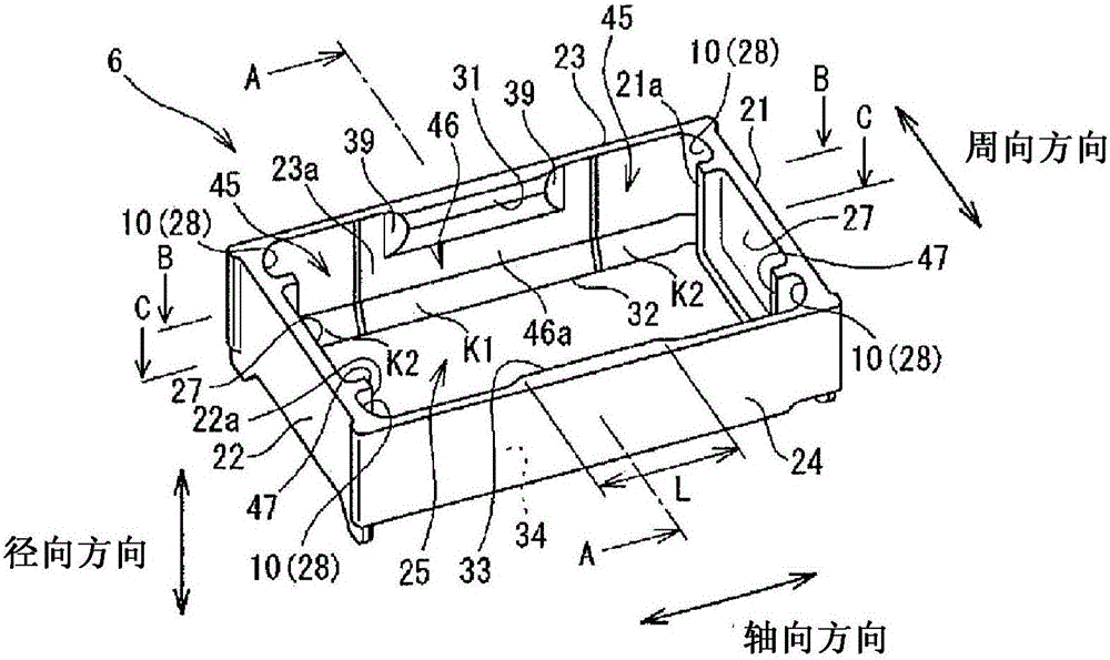
This segmented cage includes a plurality of cage segments (6), each of which has a pair of rim sections (21, 22) and a pair of column sections (23, 24). A tapered roller is incorporated into a pocket (25) from the radial outer side of each cage segment (6). The column sections (23, 24) have cage sections (31, 32, 33, 34) that are provided as protruding toward the tapered roller side on both the radial outer sides and radial inner sides thereof. The cage sections (31, 32, 33, 34) contact the outer circumferential surface of the tapered roller so as to position the tapered roller in the radial direction of the cage segment (6). The radially outward cage sections (31, 33) by which the tapered roller is incorporated into the pocket (25) are provided in the axial center region of the column sections (23, 24).

Description

technical field [0001] The present invention relates to a divided cage composed of a plurality of cage segments and a roller bearing provided with the divided cage. Background technique [0002] As a cage in which a plurality of rollers rolling between an inner ring and an outer ring in a roller bearing are retained at predetermined intervals in the circumferential direction, a divided cage composed of a plurality of cage segments is known (eg See Patent Document 1 or 2). The retainer segments are arranged circumferentially and annularly in the annular space between the inner and outer rings. Each retainer segment has a single recess that receives a single roller. [0003] In addition, as such a split cage, a "roller guide type" cage is often used. In "roller-guided" cages, the cage segments are positioned radially by rollers, respectively, preventing wear of the cage segments due to contact with the inner and outer rings. [0004] Figure 17 is a schematic explanatory v...

Claims


Application Information

Patent Timeline
IPC IPC(8): F16C33/46F16C19/36
CPCF16C19/364F16C33/467F16C33/4676F16C33/51F16C33/513F16C2300/14
Inventor 安田浩隆
Owner JTEKT CORP
Learn More