Eureka AIR delivers breakthrough ideas for toughest innovation challenges, trusted by R&D personnel around the world.

Positioning pin

A positioning pin and sliding groove technology, applied in the field of positioning pins, can solve the problems of large positioning error, blank hole size and roundness error, inconvenient removal, etc. Effect

Inactive Publication Date: 2016-10-05
肖建峰
View PDF0 Cites 3 Cited by
  • Summary
  • Abstract
  • Description
  • Claims
  • Application Information

AI Technical Summary

Problems solved by technology

[0003] Positioning pins are commonly used positioning tools in mechanical processing. They are widely used in mechanical processing. Ordinary positioning pins are generally fixed. When it is necessary to replace similar workpieces for processing, the original positioning pins must be pulled out. It is very uncomfortable to pull out Convenient, time-consuming and labor-intensive
At the same time, there are large errors in the size and roundness of the blank hole, resulting in large positioning errors, and the processing quality of the workpiece is not easy to guarantee

Method used


Image

  • Positioning pin
  • Positioning pin

Examples


Embodiment Construction

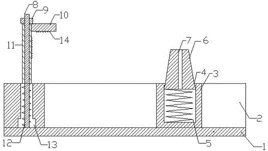
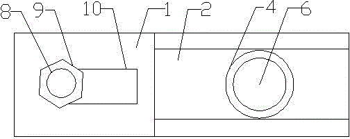
[0016] Accompanying drawing is a kind of specific embodiment of the present invention. Such as figure 1 , 2 As shown, this kind of positioning pin includes a base 1, a sliding groove 2 is provided on the base 1, a cylinder 3 is arranged in the sliding groove 2, the cylinder 3 can slide in the sliding groove 2, and the top of the cylinder 3 is a round hole 4 , the diameter of the round hole 4 is smaller than the inner diameter of the cylinder 3, a compression spring 5 is provided at the bottom of the cylinder 3, a round table 6 is arranged above the compression spring 5, the upper part of the round table 6 protrudes from the round hole 4, and the round table 6 slides with the cylinder 3 Cooperate. The round table 6 plays the positioning effect of the hair hole, and the round table 6 is provided with a vent hole 7 in the vertical direction, which is convenient for the round table to slide in the cylinder.

[0017] The adjustable clamping mechanism includes a blind hole 13 on ...


PUM


Abstract

The invention relates to the field of machining, in particular to a positioning pin. The positioning pin comprises a base and an adjustable clamping mechanism. The positioning pin is characterized in that a sliding groove is formed in the base; a cylinder capable of sliding in the sliding groove is arranged in the sliding groove; a compression spring is arranged at the bottom of the cylinder; and a circular truncated cone is arranged above the compression spring and is in sliding fit with the cylinder. The adjustable clamping mechanism comprises a blind hole in the base. An adjusting screw is fixedly arranged at the bottom of the blind hole. The adjusting screw is sequentially sleeved with an adjusting screw, a tubular body and an adjusting nut from bottom to top. A flat panel is arranged at the upper end of the tubular body. Sawteeth are arranged on the side, facing the sliding groove, of the tubular body and the lower surface of the flat panel. A vertical vent hole is formed in the circular truncated cone. The positioning pin is not affected by the size of a blank hole or the circularity error, the fit clearance between the blank hole and the positioning pin can be eliminated, positioning errors are reduced, and the positioning pin is convenient to use, capable of saving time and labor and firm in positioning.

Description

[0001] a positioning pin (1) Technical field [0002] The invention relates to the field of machining, in particular to a positioning pin. (2) Background technology [0003] Positioning pins are commonly used positioning tools in mechanical processing. They are widely used in mechanical processing. Ordinary positioning pins are generally fixed. When it is necessary to replace similar workpieces for processing, the original positioning pins must be pulled out. It is very uncomfortable to pull out Convenient, time-consuming and labor-intensive. At the same time, there are large errors in the size and roundness of the blank hole, resulting in large positioning errors, and the processing quality of the workpiece is not easy to guarantee. (3) Contents of the invention [0004] In order to make up for the deficiencies of the prior art, the present invention provides a positioning pin that is not affected by the size and roundness error of the blank hole, eliminates the fit gap ...

Claims


Application Information

Patent Timeline
Patent Type & Authority Applications(China)
IPC IPC(8): B23Q3/06
Inventor 肖建峰
Owner 肖建峰
Why Eureka
Eureka Blog
Learn More