Optical encoder

A technology of optical encoders and optical patterns, applied in the field of optical encoders, can solve the problems of increasing production costs and difficulties, limiting the maximum positioning resolution of optical encoders, etc., and achieve the effect of high positioning resolution

Active Publication Date: 2016-10-05
IND TECH RES INST
View PDF7 Cites 2 Cited by
  • Summary
  • Abstract
  • Description
  • Claims
  • Application Information

AI Technical Summary

Problems solved by technology

The high-density and high-precision sensing device also increases the production cost and difficulty, thereby limiting the highest positioning resolution that the optical encoder can judge.

Method used


Image

  • Optical encoder
  • Optical encoder
  • Optical encoder

Examples


Embodiment Construction

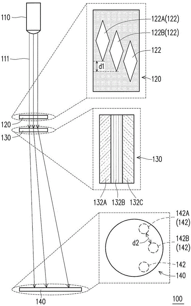
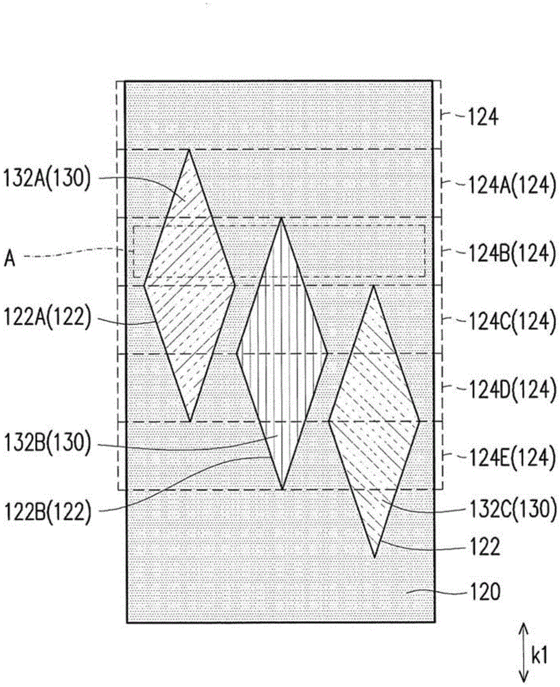
[0062] figure 1 It is a schematic diagram of an optical encoder and a top view of a positioning element, a light splitting structure, and a sensing area according to the first embodiment of the present invention. figure 2is a top view of a positioning element and a light splitting structure according to the first embodiment of the present invention. Please refer to figure 1 and figure 2 , in the first embodiment of the present invention, the optical encoder 100 includes a light emitting module 110 , a positioning element 120 and a light splitting structure 130 . The light emitting module 110 emits a light beam 111 , and the light beam 111 irradiates the irradiation area A of the positioning element 120 . The positioning element 120 includes a plurality of light-transmitting regions 122 arranged in a shifted position, and these light-transmitting regions 122 move into the irradiation area A sequentially. Since the light-transmitting regions 122 are arranged in dislocation...


PUM


Abstract

The present invention discloses an optical encoder including a light emitting module, a positioning device and a light separating structure. The light emitting module emits a light beam illuminating an illumination area of the positioning device. The positioning device includes light penetrating areas arranged in a dislocation manner. The light penetrating areas sequentially move into the illumination area. The light separating structure is disposed in the path of the light beam. The positioning device is disposed between the light emitting module and the light separating structure. When part of the light beam penetrates one of these light penetrating areas and is transmitted to the light separating structure, the light separating structure transmits the light to a sensing area and forms at least one first positioning optical pattern. The distance between two first positioning optical patterns formed by two adjacent light penetrating areas is greater than the pitch between the two adjacent light penetrating areas.

Description

technical field [0001] The present invention relates to an optical device, and in particular to an optical encoder. Background technique [0002] In the existing electronic components and mechanical components, in order to accurately grasp the rotation and movement of each component, the prior art will install an optical encoder inside the driving component such as a motor. An optical encoder is composed of an optical structure with specific information, a light source and a light sensor. Generally speaking, the optical structure has multiple regions through which light can pass. When the optical structure rotates, the optical sensor will receive a specific periodic optical signal. At this time, the optical encoder can judge the displacement, angular displacement and rotational speed of the object driven by the driving element according to the optical signal. [0003] Due to the continuous improvement of current technology for the alignment requirements between various com...

Claims


Application Information

Patent Timeline
Patent Type & Authority Applications(China)
IPC IPC(8): G01D5/32
CPCG01D5/34715G01D5/34792G01D5/3473
Inventor 陈庆昌陈易呈周明杰
Owner IND TECH RES INST
Why Eureka
Try Eureka