Timepiece comprising a repeater mechanism and a control mechanism with an integrated release lock

A technology of control mechanism and locking device, which is applied in the field of clocks and watches, can solve problems such as difficult actuation, and achieve the effect of eliminating operating errors

Active Publication Date: 2016-10-05
GLASH&XFC TTER UHRENBETRIEB
View PDF8 Cites 13 Cited by
  • Summary
  • Abstract
  • Description
  • Claims
  • Application Information

AI Technical Summary

Problems solved by technology

[0004] There is no locking device to prevent further release of the strik

Method used


Image

  • Timepiece comprising a repeater mechanism and a control mechanism with an integrated release lock
  • Timepiece comprising a repeater mechanism and a control mechanism with an integrated release lock
  • Timepiece comprising a repeater mechanism and a control mechanism with an integrated release lock

Examples


Embodiment Construction

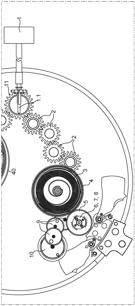
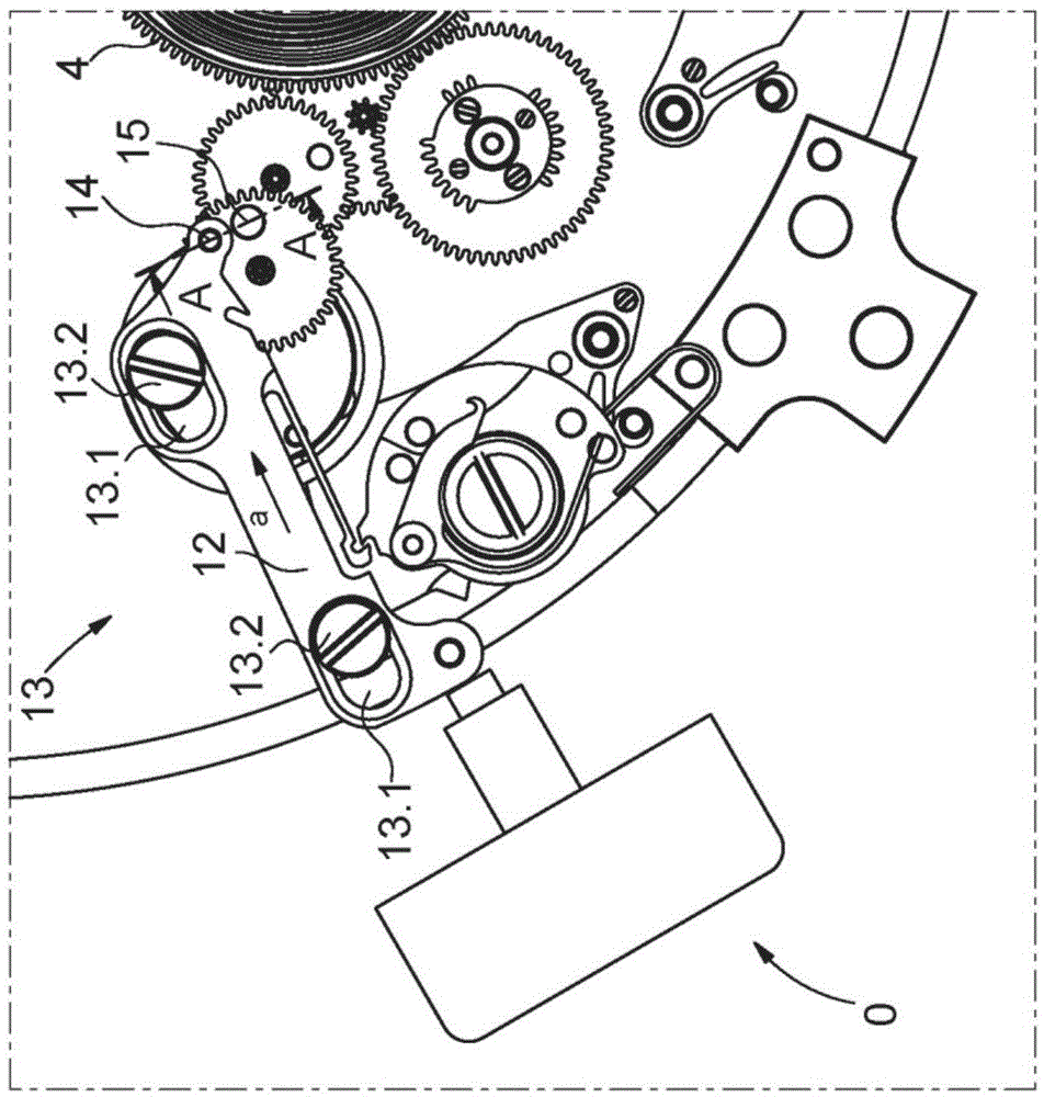
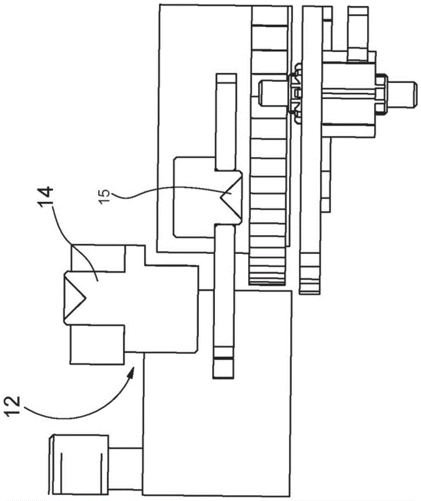
[0030] The figures below each show the structure of the control mechanism with separate winding and release means and the sequence of operations following the release of the striking mechanism which bring the control mechanism into states during the movement of the striking mechanism.

[0031] figure 1 A preferred embodiment of the winding device for tensioning the striking mechanism is shown on the right. By rotating the winding stem 1.1 of the conventional crown 1, the winding drive chain 2 is set in rotational movement. As a result, first mainspring 3 of striking mechanism barrel 4 is tensioned. As is known from clocks with self-winding, the first mainspring 3 is equipped with a sliding tensioner. By the same rotational movement, the second mainspring (not shown) of the timepiece's running barrel 40 is also tensioned; this second mainspring is also equipped with a sliding tensioning device. The two mainsprings are thus tensioned by the rotation of the winding stem until ...


PUM


Abstract

The invention relates to a timepiece including a repeater mechanism including a spring barrel (4), a control mechanism including an actuating member for releasing the repeater mechanism, a release locking device which is activated automatically immediately after releasing the repeater mechanism, the release locking device including a release lever (12) which is moveable between a rest position and a working position, the release lever (12) including a first pin (14) to block the spring barrel (4) in the rest position and to release the spring barrel (4) in the working position.

Description

technical field [0001] The invention relates to a timepiece comprising a repeater mechanism and a special control mechanism. Background technique [0002] The minute repeater has been known since the time of Breguet in the 18th century. They are designed to indicate the current time on demand by means of different beeps. The best known example of this repeater mechanism, which uses two gongs to To chime the hours as a rule, then the quarter-hours where practicable, and finally the remaining minutes, respectively. The release of the striking mechanism is actuated by the so-called winding slide, which first tensions the mainspring of the striking mechanism by means of a toothed rack meshing with a pinion provided on the striking mechanism barrel cover. At the end of travel of the slider, the movement of the striking mechanism is released, wherein in particular the cooperation between the rack and the rung determines the current time in relation to the end of travel of the s...

Claims


Application Information

Patent Timeline
IPC IPC(8): G04B1/16G04B13/00
CPCG04B1/16G04B13/00G04B21/02G04B21/06G04B21/12G04F7/089
Inventor S·戈德曼
Owner GLASH&XFC TTER UHRENBETRIEB
Why Eureka
Try Eureka