Steam cutting device

A technology of cutting equipment and steam, which is applied in welding equipment, metal processing equipment, plasma welding equipment, etc., can solve the problems of pressure, fluid supply for steam cutting equipment, etc., and achieve the effect of eliminating operation errors and simple cost

Inactive Publication Date: 2007-06-13
FRONIUS INTERNATIONAL GMBH
View PDF2 Cites 0 Cited by
  • Summary
  • Abstract
  • Description
  • Claims
  • Application Information

AI Technical Summary

Problems solved by technology

[0004] The disadvantage of this burner is that the pressure continues to exist in the burner and supply line when the steam cutting process is completed, i.e. when the burner is switched off or during standby operation
The aforementioned patent specification does not give any details about the fluid supply of the steam cutting device to the burner

Method used


Image

  • Steam cutting device
  • Steam cutting device
  • Steam cutting device

Examples


Embodiment Construction

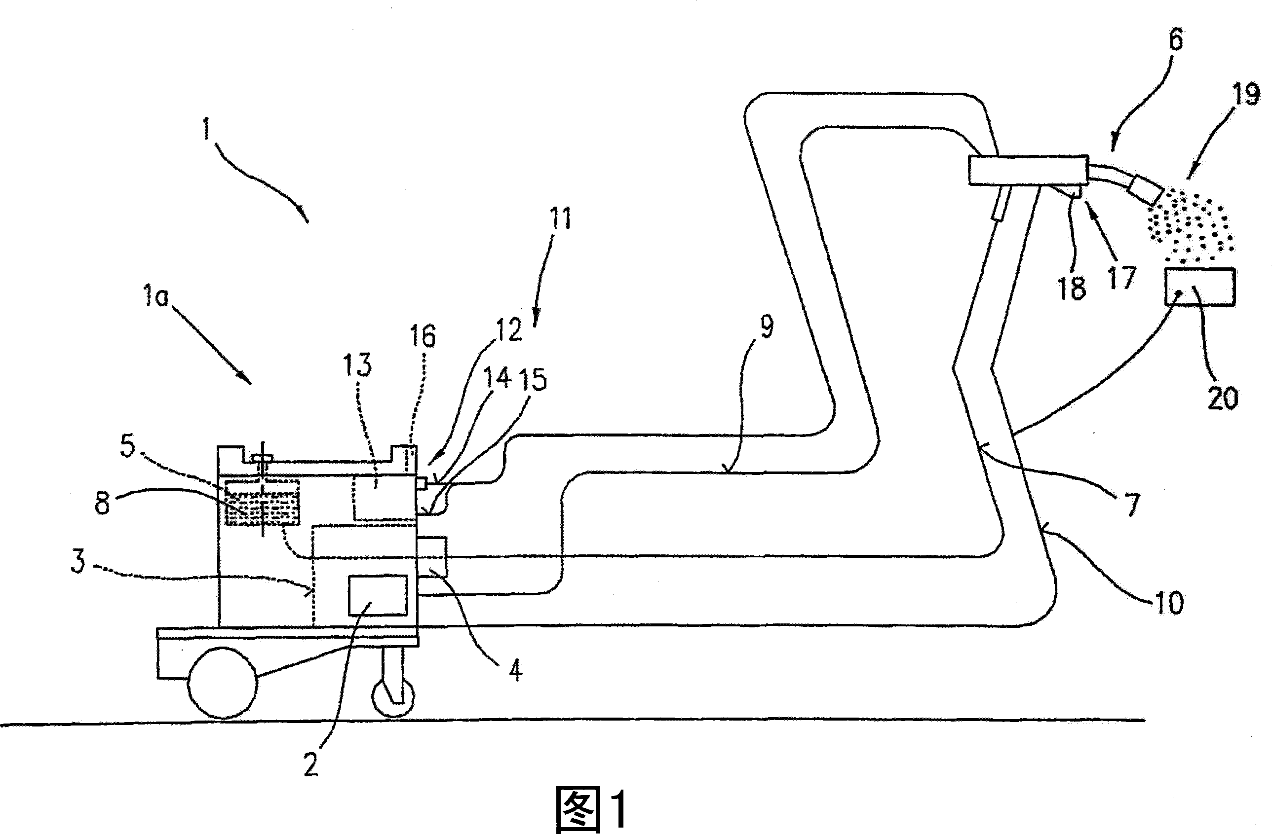
[0025] Figure 1 shows a steam cutting device 1 comprising a basic device 1a for a steam cutting process. The basic device 1 a includes a current source 2 , a control device 3 and a blocking element 4 associated with the control device 3 . The blocking element 4 is connected to the container 5 and the burner 6 via a supply line 7 in such a way that the burner 6 can be supplied with the fluid 8 provided in the container 5 . The energy supply (in particular current and voltage) of the burner 6 takes place via the lines 9 , 10 from the current source 2 .

[0026] For cooling the burner 6 , the burner 6 is connected via a cooling circuit 11 to a fluid container 13 , optionally via an interposed flow monitor 12 . During operation of the burner 6 or the base unit 1 a , a cooling circuit 11 is activated by the control device 3 , so that the burner 6 is cooled by the cooling circuit 11 . To form a cooling circuit 11 , the burner 6 is connected to a fluid container 13 via cooling line...


PUM


Abstract

The invention relates to a steam cutting device (1), comprising at least one container (5), for a fluid (8), a current source (2), a controller (3) and a burner (6), connected to the container (5), by means of a supply line (7), for generation of a steam jet exiting through a nozzle. According to the invention, such a steam cutting device (1), in which no, or almost no fluid is found in the burner in stand-by mode or after switch-off of the steam cutting device such that post-evaporation can be avoided, may be achieved, whereby a relief line (22) is connected to the supply line (7), for relieving the supply line (7) and/or the burner (6), on or after the ending of the steam cutting process. A regulation valve (24) can be provided in the relief line, which can be connected to the controller (3) itself coupled to a sensor (25), for determining the pressure in the burner (6).

Description

technical field [0001] The invention relates to a steam cutting device comprising at least one container for liquid, a current source, control means and a burner connected to said container via a supply line to generate a jet of steam expelled through a nozzle. [0002] The liquid container, current source and control means are generally arranged in the base unit connected to the burner by suitable lines. Background technique [0003] From AT 406 559 B a burner for a steam cutting method is known, which is to be connected to a control device and supply equipment. Here, a cathode and optionally an anode, a fluid supply system and channels extending in the region of the cathode are arranged in the burner. The channel can be connected to a supply line of a liquid supply system. The burner and channel respectively comprise runners or runners or longitudinal grooves. A channel extends from the anode or cathode in the direction of the supply line and is arranged between the cat...

Claims


Application Information

Patent Timeline
Patent Type & Authority Applications(China)
IPC IPC(8): B23K10/00
CPCY10T83/041B23K10/00
Inventor 哈拉尔德·朗热德尔黑里贝特·潘泽
Owner FRONIUS INTERNATIONAL GMBH
Why Eureka
Try Eureka