Supercharge Your Innovation With Domain-Expert AI Agents!

cmos rectifier diode circuit unit

A rectifier diode and circuit unit technology, applied in the field of CMOS rectifier diode circuit unit, can solve problems such as high turn-on voltage and large reverse leakage

Active Publication Date: 2018-10-09
SOI MICRO CO LTD
View PDF10 Cites 0 Cited by
  • Summary
  • Abstract
  • Description
  • Claims
  • Application Information

AI Technical Summary

Problems solved by technology

[0006] In order to overcome the problem that the reverse leakage of the CMOS diode circuit unit in the above prior art is relatively low when the turn-on voltage is low, or the turn-on voltage is high when the reverse leakage is low, the purpose of the present invention is to provide a device with low CMOS rectifier diode circuit unit with reverse leakage and low turn-on voltage

Method used


Image

  • cmos rectifier diode circuit unit
  • cmos rectifier diode circuit unit
  • cmos rectifier diode circuit unit

Examples


Embodiment Construction

[0018] The following will clearly and completely describe the technical solutions in the embodiments of the present invention with reference to the accompanying drawings in the embodiments of the present invention. Obviously, the described embodiments are only some, not all, embodiments of the present invention. Based on the embodiments of the present invention, all other embodiments obtained by persons of ordinary skill in the art without making creative efforts belong to the protection scope of the present invention.

[0019] The embodiment of the present invention provides a CMOS rectifier diode circuit unit, which not only has a lower turn-on voltage, but also has very low reverse leakage, and can be applied to an ultra-low power consumption rectifier circuit to improve the efficiency of the rectifier circuit.

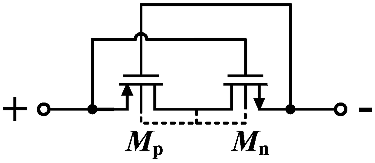
[0020] Such as Figure 4 As shown, the CMOS rectifier diode circuit unit provided by the embodiment of the present invention includes: a PMOS transistor M p , an ...


PUM


Abstract

The invention discloses a CMOS rectifier diode circuit unit. The CMOS rectifier diode circuit unit includes a PMOS transistor, an NMOS transistor, a first offset voltage source and a second offset voltage source, wherein a source electrode of the PMOS transistor is connected with a negative end of the second offset voltage source, and the source electrode of the PMOS transistor and the negative end of the second offset voltage source are connected with a positive end of a rectifier diode unit together; a grid of the PMOS transistor is connected with a negative end of the first offset voltage source; a drain electrode of the PMOS transistor is connected with a substrate of the PMOS transistor, and is connected with a drain electrode and a substrate of the NMOS transistor; a source electrode of the NMOS transistor is connected with a negative end of the first offset voltage source, and the source electrode of the NMOS transistor and the negative end of the first offset voltage source are connected with a negative end of the rectifier diode unit together; and a grid of the NMOS transistor is connected with a positive end of the second offset voltage source. The CMOS rectifier diode circuit unit is not only provided with a lower starting voltage, but also is provided with very low reverse electric leakage. The CMOS rectifier diode circuit unit is suitable for an ultra-low power consumption rectification circuit, and can effectively improve the efficiency of the rectification circuit.

Description

technical field [0001] The invention relates to the technical field of integrated circuit design, in particular to a CMOS rectifier diode circuit unit. Background technique [0002] Diode is one of the most commonly used basic electronic components. Its characteristics of forward conduction and reverse cutoff are widely used in various circuits, especially as rectifier devices in various power circuits. Traditional rectifier diodes mainly include PN junction diodes and Schottky diodes. The reverse leakage of PN junction diodes is small, but its forward conduction voltage drop is large; the forward conduction voltage drop of Schottky diodes is small, But its reverse leakage is very large, and it is not compatible with CMOS process. In order to improve the performance of the rectifier circuit and reduce power consumption, it is necessary to try to reduce the forward conduction voltage drop and reverse leakage of the diode. In addition, in order to facilitate the monolithic in...

Claims


Application Information

Patent Timeline
Patent Type & Authority Patents(China)
IPC IPC(8): H02M1/06
Inventor 刘欣刘昱张海英
Owner SOI MICRO CO LTD
Features
  • R&D
  • Intellectual Property
  • Life Sciences
  • Materials
  • Tech Scout
  • Unparalleled Data Quality
  • Higher Quality Content
  • 60% Fewer Hallucinations
Learn More