
An automatic vacuuming device for a chemical laboratory

A chemical laboratory and automatic vacuuming technology, applied in cleaning equipment, applications, household appliances, etc., can solve the problems of poor rigid support performance, low degree of automation, and low work efficiency, and achieve good rigid support and high work efficiency , fast dust removal effect

Active Publication Date: 2018-06-29
南通全昂等离子体科技有限公司
View PDF5 Cites 0 Cited by
  • Summary
  • Abstract
  • Description
  • Claims
  • Application Information

AI Technical Summary

Problems solved by technology

[0003] In order to solve the above problems, the present invention provides an automatic vacuuming device for chemical laboratories, which can solve the problems of slow dust removal and high labor intensity in existing chemical laboratories in the way of manually cleaning indoor dust with existing high-level auxiliary equipment. , low degree of automation, poor rigid support performance, poor stability and low work efficiency, etc., can realize the stable automatic dust removal function in the chemical laboratory, without manual operation, and has fast dust removal speed, good rigid support and good stability. and high work efficiency, providing a new way of automatic dust removal in chemical laboratories

Method used


Image

  • An automatic vacuuming device for a chemical laboratory
  • An automatic vacuuming device for a chemical laboratory

Examples


Embodiment Construction

[0014] In order to make the technical means, creative features, goals and effects achieved by the present invention easy to understand, the present invention will be further described below in conjunction with specific illustrations.

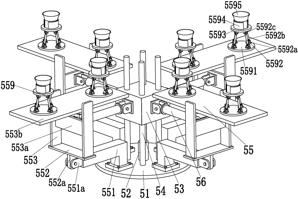
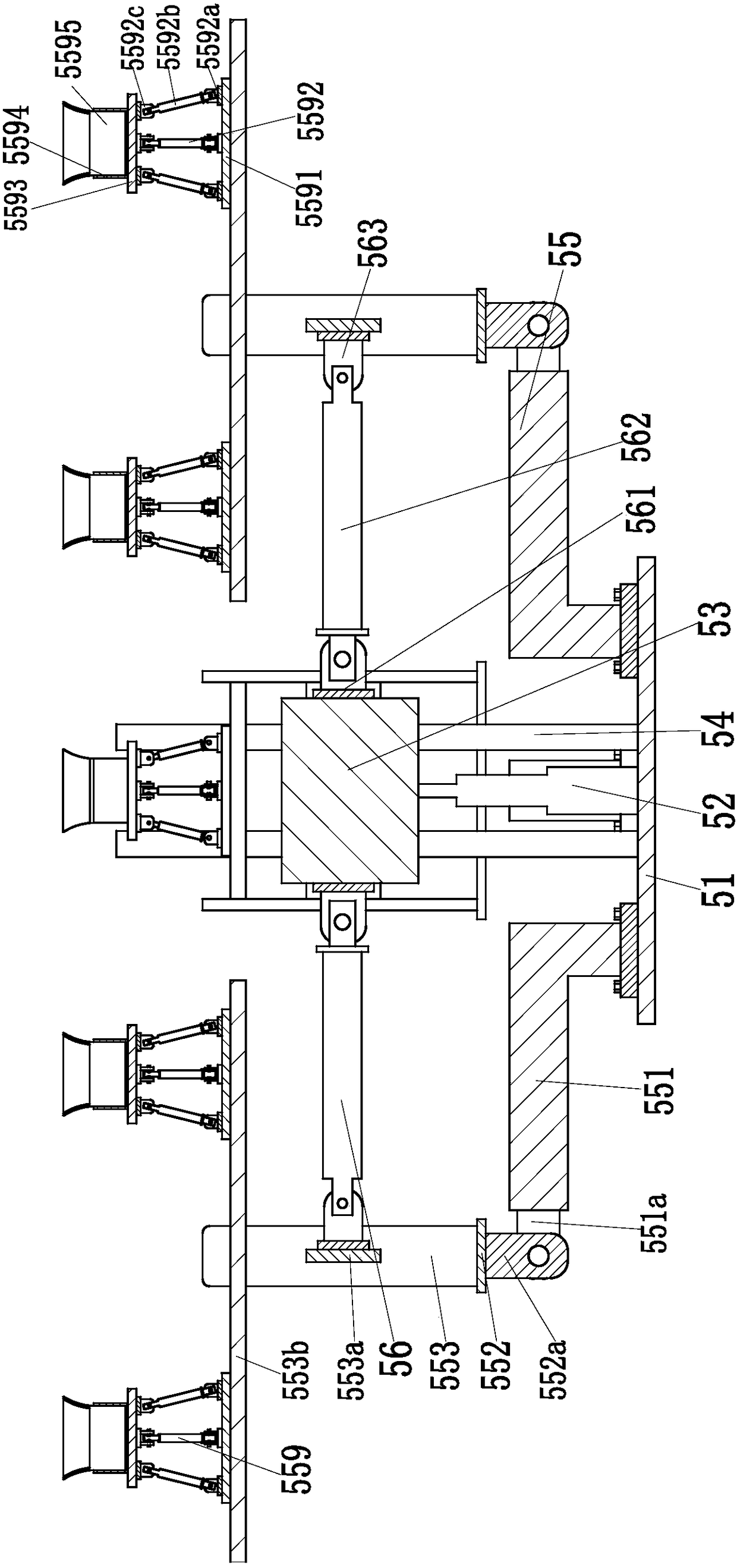
[0015] Such as figure 1 and figure 2As shown, an automatic vacuuming device for a chemical laboratory includes a support round table 51, a No. 5 hydraulic cylinder 52 is installed in the middle of the upper end surface of the support round table 51, and a square adjustment block 53 is installed on the top of the No. 5 hydraulic cylinder 52. , the square adjustment block 53 is symmetrically provided with four limit holes, and the upper end surface of the supporting round table 51 is symmetrically welded with four positioning round rods 54, and the four positioning round rods 54 are respectively installed on the four sides of the square adjustment block 53. On the two limit holes, four positioning round rods 54 play the role of limiting the move...


PUM


Abstract

The invention relates to an automatic dust collecting device used for a chemical laboratory. The automatic dust collecting device comprises a support round platform, wherein a No.5 hydraulic cylinder is mounted in the middle of the upper end surface of the support round platform, a square adjustment block is mounted on the top end of the No.5 hydraulic cylinder, four limiting holes are symmetrically formed in the square adjustment block, four positioning round bars are symmetrically welded to the upper end surface of the support round platform, and the four positioning round bars are respectively arranged on the four limiting holes of the square adjustment block in a penetrating manner; four cleaning devices are uniformly mounted on the upper end surface of the support round platform along the axis direction through screws, four angle conversion branched chains are respectively mounted between the four cleaning devices and four side surfaces of the square adjustment block, and the dedusting angle of the cleaning devices is regulated through the angle conversion branched chains and the No.5 hydraulic cylinder; each angle conversion branched chain comprises a No.4 lug base welded to the side surface of the square adjustment block. The automatic dust collecting device can realize the stable automatic dedusting function in the chemical laboratory, and therefore, an automatic dedusting novel path for the chemical laboratory is provided.

Description

technical field [0001] The invention relates to the field of chemical dust removal equipment, in particular to an automatic dust collection equipment used in chemical laboratories. Background technique [0002] In chemical laboratories, staff often use various reagents and solutions for experiments. Usually, the mixed reagents or mixed solutions of the experiment are placed in test tubes, and the test tubes are exposed on the laboratory table. The entry of any external dust may affect the experimental results. Therefore, regular dust removal must be carried out in the chemical laboratory to prevent too much dust from falling into the open test tubes in the chemical laboratory. The dust in the existing chemical laboratory is mainly concentrated on the floor, The dust on the suspended ceiling or the ceiling and the floor is usually automatically processed by the existing sweeping and dust removal robot, while the dust on the suspended ceiling and the ceiling is usually manuall...

Claims


Application Information

Patent Timeline
Patent Type & Authority Patents(China)
IPC IPC(8): A47L11/38A47L11/40
CPCA47L11/38A47L11/40A47L11/4063A47L11/4094
Inventor 金海华
Owner 南通全昂等离子体科技有限公司
Learn More