Ultrasonic pulse Doppler imaging method and device

A technology of pulse Doppler and imaging method, which is applied in ultrasonic/sonic/infrasonic diagnosis, sonic diagnosis, infrasonic diagnosis and other directions to achieve the effect of reducing the number of orders

Active Publication Date: 2016-10-12
VINNO TECH (SUZHOU) CO LTD
View PDF7 Cites 8 Cited by
  • Summary
  • Abstract
  • Description
  • Claims
  • Application Information

AI Technical Summary

Problems solved by technology

[0004] In view of this, an embodiment of the present invention provides an ultrasonic pulse Doppler imaging method and device to solve the technical problems in the prior art when the blood flow is at a high flow rate

Method used


Image

  • Ultrasonic pulse Doppler imaging method and device
  • Ultrasonic pulse Doppler imaging method and device
  • Ultrasonic pulse Doppler imaging method and device

Examples


Embodiment 1

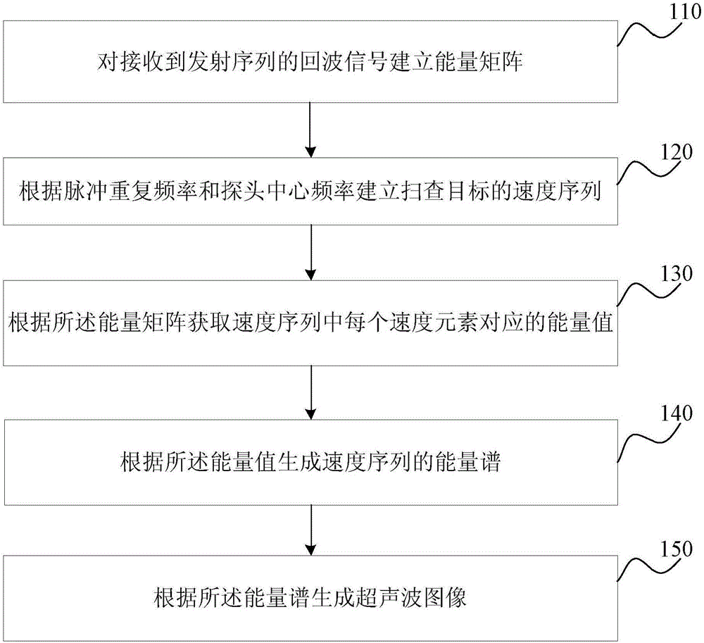
[0025] figure 1 It is a schematic flow chart of the ultrasonic pulse Doppler imaging method provided in Embodiment 1 of the present invention. This embodiment is applicable to imaging based on echo signals of ultrasonic pulses, and the method can be performed by an ultrasonic pulse Doppler imaging device. The device can be implemented by software / hardware, and can be integrated into a corresponding ultrasonic detection system.

[0026] see figure 1 , the ultrasonic pulsed Doppler imaging method, comprising:

[0027] S110. Establish an energy matrix for echo signals of the received transmission sequence.

[0028] The ultrasonic device encodes the transmitted scanning signal. Exemplarily, according to the size of the sampling gate, the time length of the transmitting pulse is determined, that is, TimeOfFM=2*SV / c, where SV is the size of the sampling gate, and C is the speed of sound. Usually 1540m / s is desirable. Calculate the frequency of each scan signal in the scan sequen...

Embodiment 2

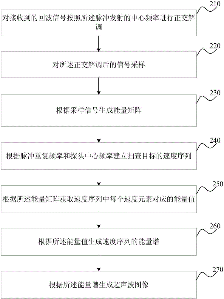
[0044] figure 2 It is a schematic flowchart of the ultrasonic pulse Doppler imaging method provided by the second embodiment of the present invention. This embodiment is optimized on the basis of the above-mentioned embodiments. In this embodiment, the specific optimization of establishing an energy matrix for the received echo signals of the transmission sequence is as follows: the received echo signals are transmitted according to the center frequency of the pulse performing quadrature demodulation; sampling the quadrature demodulated signal; generating an energy matrix according to the sampled signal.

[0045] Correspondingly, the ultrasonic pulse Doppler imaging method provided in this embodiment specifically includes:

[0046] S210. Perform quadrature demodulation on the received echo signal according to the center frequency of the pulse transmission.

[0047] For the echo signal of the sent scanning line, quadrature demodulation is performed according to the center fr...

Embodiment 3

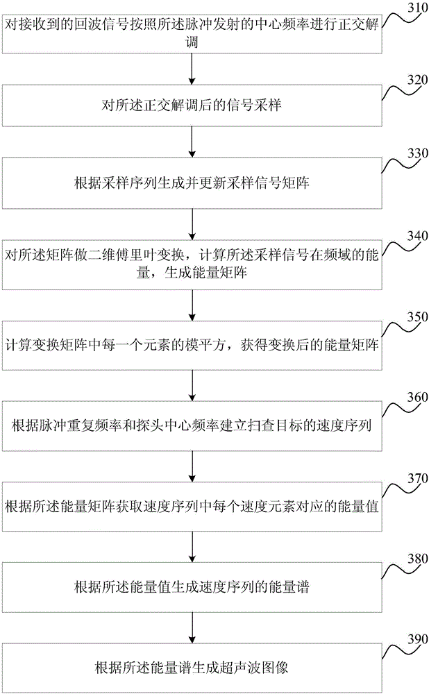
[0058] image 3 It is a schematic flow chart of the ultrasonic pulse Doppler imaging method provided in Embodiment 3 of the present invention. This embodiment is optimized on the basis of the above embodiments. In this embodiment, the generation of the energy matrix according to the sampling signal is specifically optimized as follows: generating and updating the sampling signal matrix according to the sampling sequence; performing two-dimensional Fusion calculation on the matrix Liye transform, calculating the energy of the sampled signal in the frequency domain to generate an energy matrix; calculating the square of the modulus of each element in the matrix to obtain a transformed energy matrix.

[0059] Correspondingly, the ultrasonic pulse Doppler imaging method provided in this embodiment specifically includes:

[0060] S310. Perform quadrature demodulation on the received echo signal according to the center frequency of the pulse transmission.

[0061] S320. Sampling t...


PUM


Abstract

The invention discloses an ultrasonic pulse Doppler imaging method and device. The method comprises the steps that an energy matrix is established for echo signals of a received transmitting sequence; a speed sequence for scanning a target is established according to pulse repetition frequency and the central frequency of a probe; energy values corresponding to all speed elements in the speed sequence are obtained according to the energy matrix; an energy spectrum of the speed sequence is generated according to the energy values; an ultrasonic image is generated according to the energy spectrum. The order of a coding compression filter can be effectively reduced, and Doppler imaging can be achieved without a large calculation amount.

Description

technical field [0001] The invention relates to the technical field of ultrasonic pulse imaging, in particular to an ultrasonic pulse Doppler imaging method and device. Background technique [0002] With its unique characteristics, such as real-time, dynamic blood flow and Doppler imaging, ultrasonic diagnostic instrument (B-ultrasound machine) has become one of the indispensable means of auxiliary diagnosis in modern medicine. Among them, pulsed Doppler imaging can conveniently and quickly measure the specific flow velocity of blood flow, and has become a criterion for judging certain diseases in clinical diagnosis. [0003] In the traditional coded emission pulse Doppler imaging technology, the blood flow velocity will have a greater impact on the pulse compression. When the blood flow is at a high flow velocity, the echo will change due to the Doppler effect. As a result, the pulse compression filter designed according to the original coding sequence will cause the signa...

Claims


Application Information

Patent Timeline
Patent Type & Authority Applications(China)
IPC IPC(8): A61B8/06
CPCA61B8/06A61B8/488A61B8/5207
Inventor 郭建军吴方刚
Owner VINNO TECH (SUZHOU) CO LTD
Why Eureka
Try Eureka