
Sectioned inverted mounting method of stirring device of decomposing tank

A technology of a stirring device and an installation method, which is applied to a mixer with a rotating stirring device, a hoisting device, and accessories of a mixer, etc., can solve the problems of difficult installation of stirring fan blades, high construction risk factor, insufficient tank position, etc. The effect of avoiding allowable errors, reducing the number of reverse shipments, and reducing the risk factor

Inactive Publication Date: 2016-10-12
TIANJIN 20 CONSTR
View PDF2 Cites 7 Cited by
  • Summary
  • Abstract
  • Description
  • Claims
  • Application Information

AI Technical Summary

Problems solved by technology

[0003] 1. Assemble the stirring shaft from the outside as a whole, and hoist it in from the top of the tank. Most of the tanks are above 40m in height, and the height of the stirring shaft after assembly is more than 30 meters. The overall weight is about 9t. It is difficult to meet the requirements with a 500t truck crane. , making the cost of machinery increase sharply
[0004] 2. Put one single piece into the tank, then assemble it into a whole in the tank, and lift it up, but the stirring shaft is too long, the position of the tank is not enough, and the stirring shaft will be deformed due to improper operation
[0005] 3. Set up a full house of scaffolding in the tank for formal installation. The entire installation process is all high-altitude operations. The construction risk factor is high, and the construction efficiency is low, the cost is high, and the subsequent mixing fan blades are difficult to install.

Method used


Image

  • Sectioned inverted mounting method of stirring device of decomposing tank

Examples


Embodiment Construction

[0024] The present invention will be further described below in conjunction with the accompanying drawings.

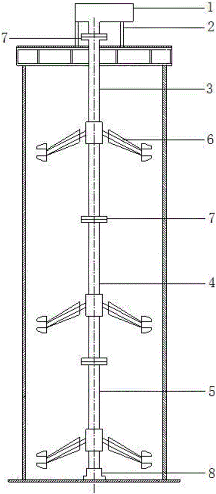
[0025] The stirring device is mainly composed of a motor and a reducer 1, a frame 2, a stirring shaft (mostly divided into three sections, which are divided into the first stirring shaft 3, the second stirring shaft 4 and the third stirring shaft 5 from top to bottom), stirring fan blades 6. It is composed of the bottom bearing frame and other parts, with a total weight of about 20 tons.

[0026] The whole stirring device is mainly suspended by the reducer 1 installed on the top of the tank, and the bottom bearing frame does not bear the axial load, but only limits the radial swing of the stirring shaft.

[0027] as attached figure 1 As shown, a segmented upside-down installation method of a decomposition tank stirring device includes the following steps: first, two hoists are installed on both sides of the installation hole of the reducer 1 on the top of the tank, an...


PUM


Abstract

The invention discloses a sectioned inverted mounting method of a stirring device of a decomposing tank. The sectioned inverted mounting method comprises the following steps: firstly, mounting two sets of winches at the two sides of a mounting hole of a tank top speed reducer; secondly, carrying out leveling adjustment on foundations of the tank top speed reducer and a rack and mounting the speed reducer and the rack; then, matching a truck crane with the tank top winches; inversely conveying and assembling a first stirring shaft and stirring blades thereof in a tank body; after the assembling is finished, hoisting the first stirring shaft by utilizing the tank top winches to be in butt joint and fastened with an upper speed reduced through a flange; after the first stirring shaft is mounted, mounting a second stirring shaft and a third stirring shaft and so on according to the mounting method; finally, mounting a bottom bearing and a base according to the height from the lower end of the third stirring shaft to a base plate. The stirring shafts are accurate to mount and the straightness and perpendicularity of the stirring shafts can be guaranteed; tight combination of the bottom bearing, the base and the stirring shafts can be realized; the cost is saved and danger coefficients of construction are also reduced.

Description

technical field [0001] The invention relates to an installation method of a stirring device, in particular to a segmented upside-down installation method of a stirring device of a decomposition tank. Background technique [0002] At present, most chemical cylindrical steel storage tanks are equipped to prevent the storage liquid from settling, or to make the solution uniform. There are stirring devices in the cylindrical steel storage tanks. The installation of the stirring shaft of the traditional stirring device mainly includes the following: methods: [0003] 1. Assemble the stirring shaft from the outside as a whole, and hoist it in from the top of the tank. Most of the tanks are over 40m in height, and the height of the stirring shaft after assembly is more than 30 meters. The overall weight is about 9t, and it is difficult to meet the requirements with a 500t truck crane. , causing a sharp increase in mechanical costs. [0004] 2. Put one single piece into the tank, ...

Claims


Application Information

Patent Timeline
Patent Type & Authority Applications(China)
IPC IPC(8): B01J19/18B01F7/18B01F15/00B66D3/06B66D1/28
CPCB01J19/18B66D1/28B66D3/06B01J2219/00022B01F27/90B01F35/40
Inventor 李凯李宝玉王见胜常喜王亚敏李晶王雪陈维坤王桂川张媛媛
Owner TIANJIN 20 CONSTR
Learn More