
Bending device for circular arc coaming plate of radiator air guide cover

The technology of a bending device and an air guide cover is applied in the field of radiator air guide cover production, which can solve the problems of low production efficiency, unsightly appearance of the wind cover, and difficulty in guaranteeing the circular arc.

Inactive Publication Date: 2017-12-08
安徽汇展热交换系统股份有限公司
View PDF14 Cites 0 Cited by
  • Summary
  • Abstract
  • Description
  • Claims
  • Application Information

AI Technical Summary

Problems solved by technology

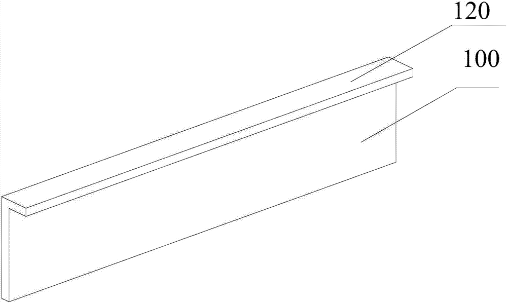
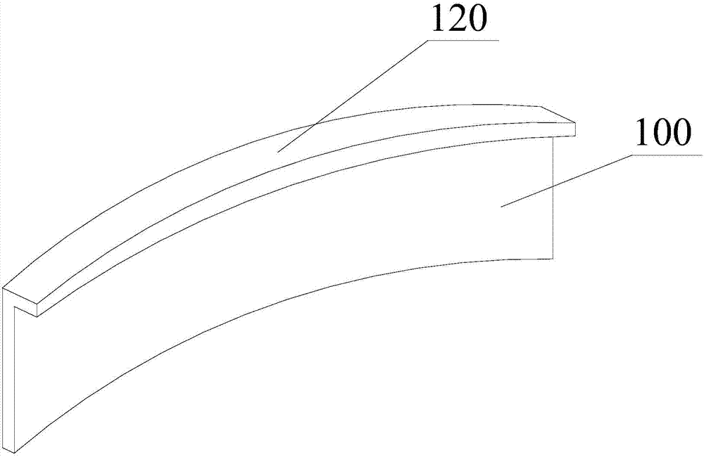
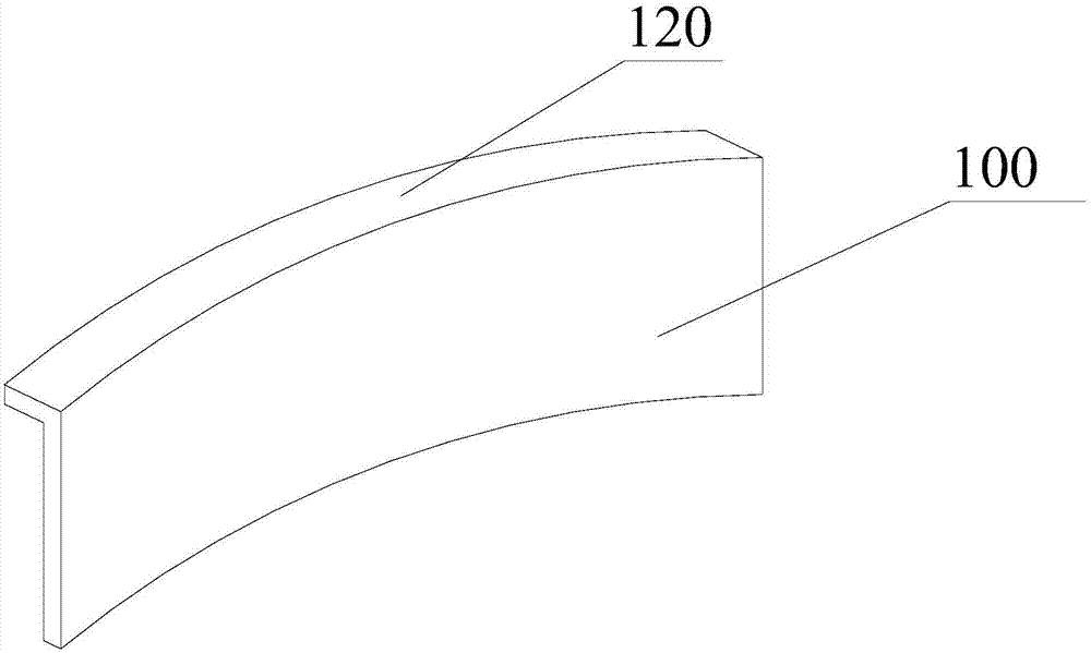
In order to make all the air inhaled by the fan pass through the radiator to improve the efficiency of the fan and enhance the heat dissipation capacity of the radiator, the radial gap between the fan and the radiator windshield is generally about 20mm, and the maximum should not exceed 2.5% of the fan diameter. For every 1% increase in the ratio of the radial gap to the fan diameter, the fan flow rate will drop by 2.5-4%, and the efficiency will drop by 2-3%. In the process of wind hood, there are certain requirements for the arc of the arc of the wind guide hood, such as figure 1 , figure 2 , image 3 As shown, the arc coaming includes the arc coaming body 100 and the bending edge 120. During the manufacturing process, the arc coaming of the air duct can be made into two sides, the bending edge 120 turned inward and the bent edge 120 turned outward. This kind of structure, but the current equipment is different to produce arc enclosures with different curvatures, and the production efficiency is low, the arc is difficult to guarantee, and the appearance of the air shield is not beautiful.

Method used


Image

  • Bending device for circular arc coaming plate of radiator air guide cover
  • Bending device for circular arc coaming plate of radiator air guide cover
  • Bending device for circular arc coaming plate of radiator air guide cover

Examples


Embodiment Construction

[0020] refer to Figure 4 , the present invention proposes a radiator wind guide cover circular arc coaming bending device, including a workbench 1, an auxiliary bending mechanism, a first bending mechanism, a second bending mechanism, a third bending mechanism and, wherein,

[0021] Auxiliary bending mechanism comprises auxiliary bending wheel 22 and first supporting shaft 21, and first supporting shaft 21 is vertically arranged on the workbench 1, and auxiliary bending wheel 22 is installed on the first supporting shaft 21, and auxiliary bending wheel 22 The outer periphery is provided with the first arc-shaped groove 23, the second arc-shaped groove 24 and the third arc-shaped groove sunken to its center and the first arc-shaped groove 23, the second arc-shaped groove 24, and the third arc-shaped groove have different radius of curvature.

[0022] The first bending mechanism comprises a first bending wheel 31, a second support shaft 32 and a first clamping device for clamp...


PUM


Abstract

The invention provides a radiator wind scooper arc coaming bending device which comprises a working table, an auxiliary bending mechanism, a first bending mechanism, a second bending mechanism and a third bending mechanism. The auxiliary bending mechanism comprises an auxiliary bending wheel and a first supporting shaft. A first arc-shaped groove, a second arc-shaped groove and a third arc-shaped groove which are sunken towards the center of the auxiliary bending wheel are formed in the periphery of the auxiliary bending wheel. The first arc-shaped groove, the second arc-shaped groove and the third arc-shaped groove have different curvature radiuses. A first bending wheel is arranged opposite to the first arc-shaped groove and can move in the radial direction of the auxiliary bending wheel. A second bending wheel is arranged opposite to the second arc-shaped groove and can move in the radial direction of the auxiliary bending wheel. A third bending wheel is arranged opposite to the third arc-shaped groove and can move in the radial direction of the auxiliary bending wheel. The radiator wind scooper arc coaming bending device can manufacture arc coamings with the different curvature radiuses, can adapt to bending of the arc coamings with the different thicknesses, and can effectively ensure the arc degree of the arc coamings.

Description

technical field [0001] The invention relates to the technical field of making a radiator air guide cover, in particular to a bending device for a radiator air guide cover arc enclosure. Background technique [0002] When the engine is arranged longitudinally on the frame, the fan is generally mounted on the water pump shaft and driven by the same V-belt that drives the water pump and generator. When the fan rotates, it sucks in air, and the air flows through the radiator along the axial direction of the fan rotation shaft, so as to enhance the heat dissipation capacity of the radiator and accelerate the cooling of the coolant. A wind guide cover is installed around the fan, so that all the air sucked in by the fan passes through the radiator, so as to improve the efficiency of the fan. At present, there are three kinds of commonly used windshield materials: thin plate type, engineering plastics and glass fiber reinforced plastics. Common thin plate materials include hot pl...

Claims


Application Information

Patent Timeline
Patent Type & Authority Patents(China)
IPC IPC(8): B21D5/08
CPCB21D5/083
Inventor 刘军魏柏平姚玉杰
Owner 安徽汇展热交换系统股份有限公司
Learn More